1
/
of
4
Uploader
Case 1816, 1816B, 1816C Uni-Loader Service Manual Workshop Guide
Case 1816, 1816B, 1816C Uni-Loader Service Manual Workshop Guide
Regular price
$34.00 USD
Regular price
Sale price
$34.00 USD
Unit price
/
per
Taxes included.
Shipping calculated at checkout.
Couldn't load pickup availability
Manual Included:
Service Manual:
598 pages
Specifications:
Brand:
Case
Model:
1816, 1816B and 1816C
Type:
Skidsteer
Manuals:
Service Manual
Publication Numbers:
8-410105 (March 1982)
Language:
English
Format:
PDF
Description
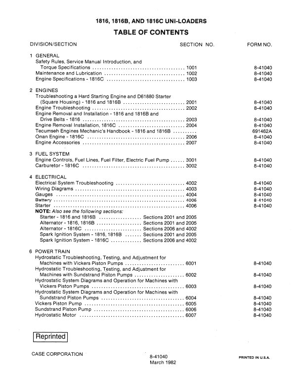
Table of Contents
General
Engines
Fuel System
Electrical
Power Train
Brakes
Hydraulics
Mounted Equipment
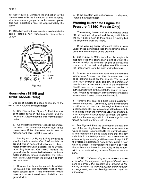
Manual Extract Checking Warning Buzzer for Engine Oil Pressure (1816C Models Only)
The warning buzzer makes a loud noise when the engine is stopped and the key switch is in the RUN position, or the engine is running but the engine oil pressure is low.
If the warning buzzer does not make a noise under these conditions, use the following procedure to find the cause of the problem:
1. Make sure that the engine is stopped. Find the connection point at which the jumper wire for the switch for engine oil pressure is connected to the main wiring harness. Disconnect the jumper wire from the main wiring harness.
2. Connect one ohmmeter lead to the end of the jumper wire. Connect the other ohmmeter lead to a good ground point on the engine. The ground point must be free of paint and dirt. The ohmmeter needle must move toward zero. If the ohmmeter needle does not move toward zero, the problem is in the jumper wire or the switch for engine oil pressure.
Repair as necessary. If the ohmmeter needle moves toward zero, continue with step 3.
3. Remove the seat and heat shield assembly from the machine. Turn the key switch to the RUN position but do not start the engine. Use a voltmeter to check for system voltage at the key switch terminal to which the warning buzzer is connected.
If the voltage indication is not correct at the terminal, install a new key switch. If the voltage indication is correct, continue with step 4.
4. See Figure 5. Find the connection point at the top of the warning buzzer. The jumper wire for the warning buzzer is connected to the warning buzzer at this connection point. Make sure that the key switch is in the RUN position. Use a voltmeter to check for system voltage at the connection point. If the voltage indication is not correct, install a new warning buzzer. If the voltage indication is correct, the problem is a break in continuity in the jumper wire or the main wiring harness. Repair as necessary.
Share