1
/
of
4
Uploader
Case O&K RH Plus Excavator Service Manual Workshop Guide
Case O&K RH Plus Excavator Service Manual Workshop Guide
Regular price
$35.00 USD
Regular price
Sale price
$35.00 USD
Unit price
/
per
Taxes included.
Shipping calculated at checkout.
Couldn't load pickup availability
Manual Included:
Workshop Manual:
577 pages
Specifications:
Brand:
Case
Model:
Case O&K RH Plus
Type:
Excavator
Manuals:
Workshop Manual
Publication Numbers:
8-44660 (February 1986)
Language:
English
Format:
PDF
Description
Table of Contents
Section 1 GENERAL INFORMATION
Group 1 Precautions for Disassembly and Assembly ……………………. W1-1
Group 2 Tightening Torque ………………………………………………………… W1-2
Section 2 UPPERSTRUCTURE
Group 1 Cab …………………………………………………………………………..W2-1
Group 2 Air Conditioner ……………………………………………………………W2-2
Group 3 Counterweight …………………………………………………………….W2-3
Group 4 Main Frame ………………………………………………………………..W2-4
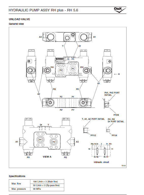
Group 5 Pump Device ………………………………………………………………W2-5
Group 6 Control Valve ………………………………………………………………W2-6
Group 7 Swing Device ……………………………………………………………..W2-7
Group 8 Pilot Valve …………………………………………………………………..W2-8
Group 9 Solenoid Valve Unit ……………………………………………………..W2-9
Section 3 UNDERCARRIAGE
Group 1 Swing Bearing …………………………………………………………….W3-1
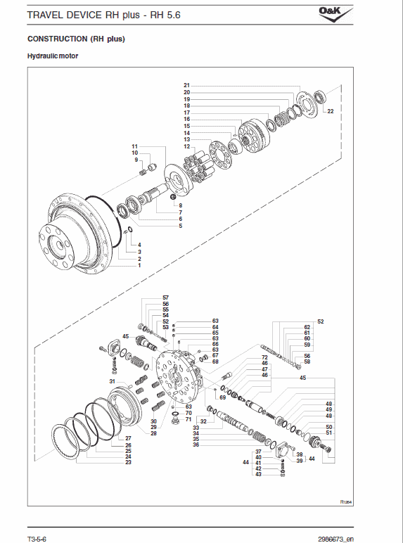
Group 2 Travel Device ………………………………………………………………W3-2
Group 3 Swivel Joint ………………………………………………………………..W3-3
Group 4 Track Adjuster …………………………………………………………….W3-4
Group 5 Front Idler …………………………………………………………………..W3-5
Group 6 Upper and Lower Roller ……………………………………………….W3-6
Group 7 Tracks……………………………………………………………………….. W3-7
Group 8 Sprocket ……………………………………………………………………. W3-8
Section 4 FRONT ATTACHMENT
Group 1 Front Attachment ………………………………………………………… W4-1
Group 2 Cylinders …………………………………………………………………… W4-2
Manual Extract : BUCKET CIRCUIT
This section describes the following: 1. Bucket digging pilot circuit.
2. Auto accel operation.
3. Constant control of standby flow rate.
4. Bucket digging main circuit.
1. BUCKET DIGGING PILOT CIRCUIT
Mechatronics:
1. When the operation for bucket digging is performed, the pilot proportional secondary pressure is delivered through port 1 of the right pilot valve (10), flows to PBc port of the control valve (2), and acts on the low pressure sensor (SE-1), and at the same time the bucket spool is switched.
2. The voltage output by the low pressure sensor (SE-1) sent to the mechatro controller and is signal processed, and then the mechatro controller outputs the command current to increase the pump flow rate to solenoid proportional valve (PSV-P1) on the P1 pump side. P1 pump proportional valve increases the flow rate by the pump positive control operation. (Refer to
Share