1
/
of
4
Uploader
Challenger MT565B, MT575B, MT585B, MT595B Tractor Workshop Manual Workshop Guide
Challenger MT565B, MT575B, MT585B, MT595B Tractor Workshop Manual Workshop Guide
Regular price
$45.00 USD
Regular price
Sale price
$45.00 USD
Unit price
/
per
Taxes included.
Shipping calculated at checkout.
Couldn't load pickup availability
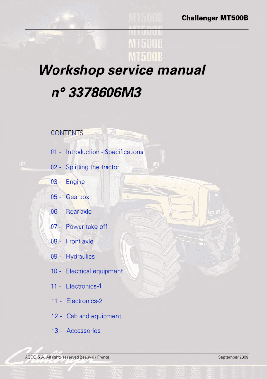
Challenger MMT565B, MT575B, MT585B, MT595B Tractor Workshop Manual (3378606M3) : 3753 Pages
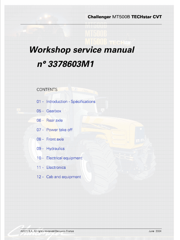
Challenger MT565B, MT575B, MT585B, MT595B TechStar CVT Tractor Workshop Manual : 2982 Pages
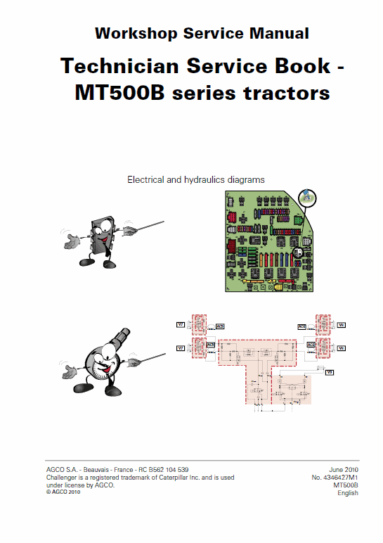
Technician Service Book MT500B (Schematics and Electronics) : 282 Pages
Parts Catalog Manual: 955 Pages & 612 Pages
Description
Challenger MT565B, MT575B, MT585B, MT595B Tractor Repair Workshop Manual
Manual for:
AGCO Challenger
MT500B Series Tractor
Format: PDF
Book Number: 3378606M3 & 3378603M1 * 3378603M7
English
Issued June 2010
Challenger MT565B, MT575B, MT585B, MT595B Tractor Workshop Manual (3378606M3) : 3753 Pages
Challenger MT565B, MT575B, MT585B, MT595B TechStar CVT Tractor Workshop Manual : 2982 Pages
Technician Service Book MT500B (Schematics and Electronics) : 282 Pages
Parts Catalog Manual: 955 Pages & 612 Pages
Challenger MT500B Series Manual TABLE OF CONTENTS
Introduction
Separation of assemblies
Engine
Clutch
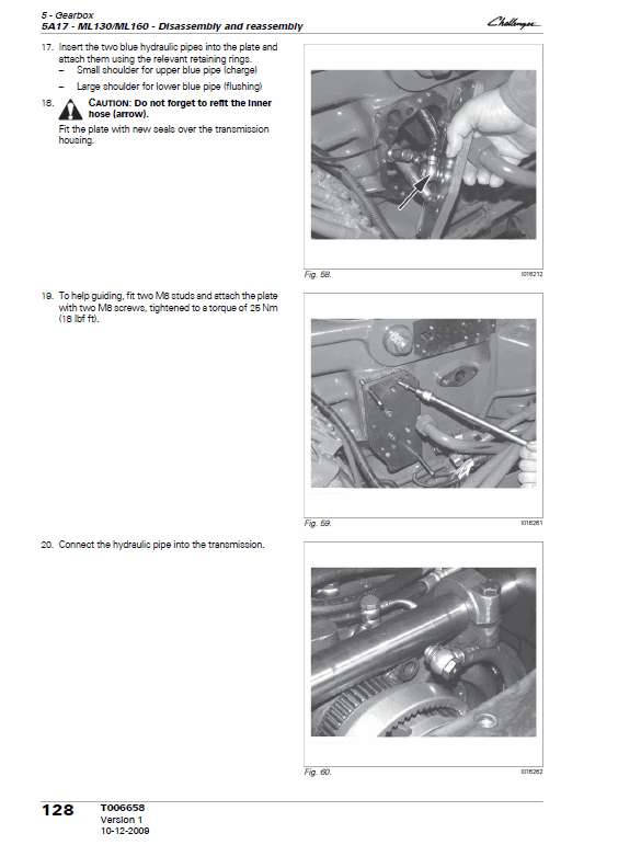
Gearbox
Rear Axle
Power Take off
Front Axle
Hydraulics
Electrical Equipment
Electronics 1
Electronics 2
Cab
Accessories
Services Tools
MT565B, MT575B, MT585B, MT595B Manual
Lubrication
The oil from the lubrication system coming from the tractor's 5 bar valve is sent to the lower shaftline and the upper shaftline of the gearbox. A network of channels and ports in the gearbox channels the oil to the parts requiring lubrication.
Selecting ratios
The range is selected by two double cone synchronisers.
Each synchroniser is engaged individually.
The synchronisers are controlled by two selector rails and two forks. Each selector rail has a double acting piston, which allows range shifting. This piston is controlled hydraulically via the tractor's 21 bar hydraulic system.
Four solenoid valves L52, L53, L54 and L55 (Fig. 2) located on the right-hand side of the gearbox control selector rail movement.
Four switches L56, L57, L58 and L59 (Fig. 2) inform the controller of the selector rail positions.
NOTE: The switches are pressed in by pins (131) (Fig. 3) controlled by the selector rails.
Each range has a solenoid valve and switch (see table below).
Share


