1
/
of
4
Uploader
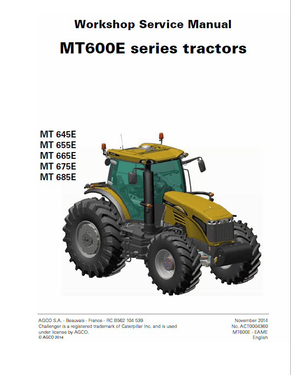
Challenger MT645E, MT655E, MT665E, MT675E, MT685E Tractor Workshop Manual Workshop Guide
Challenger MT645E, MT655E, MT665E, MT675E, MT685E Tractor Workshop Manual Workshop Guide
Regular price
$40.00 USD
Regular price
Sale price
$40.00 USD
Unit price
/
per
Taxes included.
Shipping calculated at checkout.
Couldn't load pickup availability
Challenger MT645E, MT655E, MT665E, MT675E, MT685E Tractor Workshop Manual : 1790 Pages
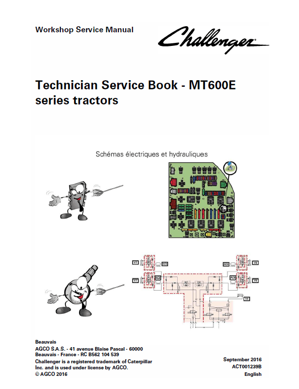
Technician Service Book MT600E (Schematics and Electronics) : 350 Pages
Parts Catalog MT600E: 392 Pages
Description
Challenger MT645E, MT655E, MT665E, MT675E, MT685E Tractor Repair Workshop Manual
Manual for:
AGCO Challenger
MT600E Series Tractor
November 2014
No. ACT0004360
North America
English
Format: PDF
Challenger MT645E, MT655E, MT665E, MT675E, MT685E Tractor Workshop Manual : 1790 Pages
Technician Service Book MT600E (Schematics and Electronics) : 350 Pages
Parts Catalog MT600E: 392 Pages
Challenger MT600E Series Manual TABLE OF CONTENTS
Introduction
Separation of assemblies
Engine
Clutch
Gearbox
Rear Axle
Power Take off
Front Axle
Hydraulics
Electricity
Electronics
Cab
Accessories
Services Tools
MT645E, MT655E, MT665E, MT675E, MT685E Manual Error Code
Compressor
The compressor, its clutch and pulley form a removable assembly.
The compressor compresses the low-pressure R134a refrigerant gas to high pressure and allows the refrigerant to flow in the system.
Electromagnetic clutch
Allows engagement and disengagement of the compressor depending on system requirements.
The coupling comprises two main parts: the stationary induction coil (continuous induction field) and the rotor.
The induction coil is fitted directly onto the compressor. The grooved pulley is fitted to the tapered end of the crankshaft. The current transmitted to the coil creates a magnetic field, and the disc is magnetically pulled against the pulley. The compressor starts running. When the current is stopped, the rotor is demagnetised and the mechanical coupling is broken.
When changing one of the following parts: evaporator, condenser, dryer, compressor or regulator, it is necessary to drain the system, taking the precautions stated in the refilling and maintenance section.
Condenser
The condenser receives high pressure, high temperature refrigerant gas from the compressor and changes it into high pressure pre-cooled liquid. It is designed to withstand variations in temperature between the hot refrigerant in gas form and the cold air outside. As the refrigerant cools, the gas turns to liquid. This cooling is achieved by exposing it to a cold air flow (vehicle speed, motor fan). The refrigerant temperature in the condenser varies between 49 °C and 77 °C for pressures of 10,5 bar to 21 bar.
If it is necessary to replace the condenser: avoid damaging the cooling fins in order to ensure the maximum operating efficiency.
Share


