1
/
of
4
Uploader
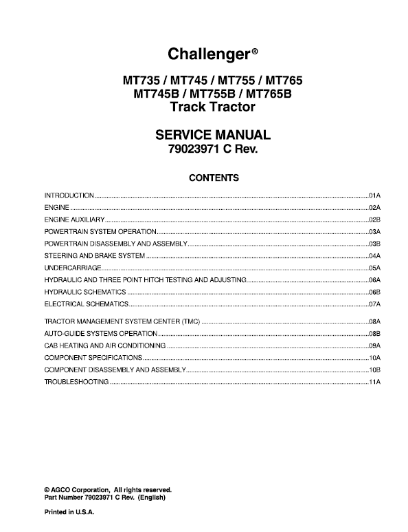
Challenger MT735, MT745, MT755, MT765 Tractor Service Manual Workshop Guide
Challenger MT735, MT745, MT755, MT765 Tractor Service Manual Workshop Guide
Regular price
$40.00 USD
Regular price
Sale price
$40.00 USD
Unit price
/
per
Taxes included.
Shipping calculated at checkout.
Couldn't load pickup availability
Challenger MT735, MT745, MT755, MT765 Tractor Workshop Manual : 2771 Pages
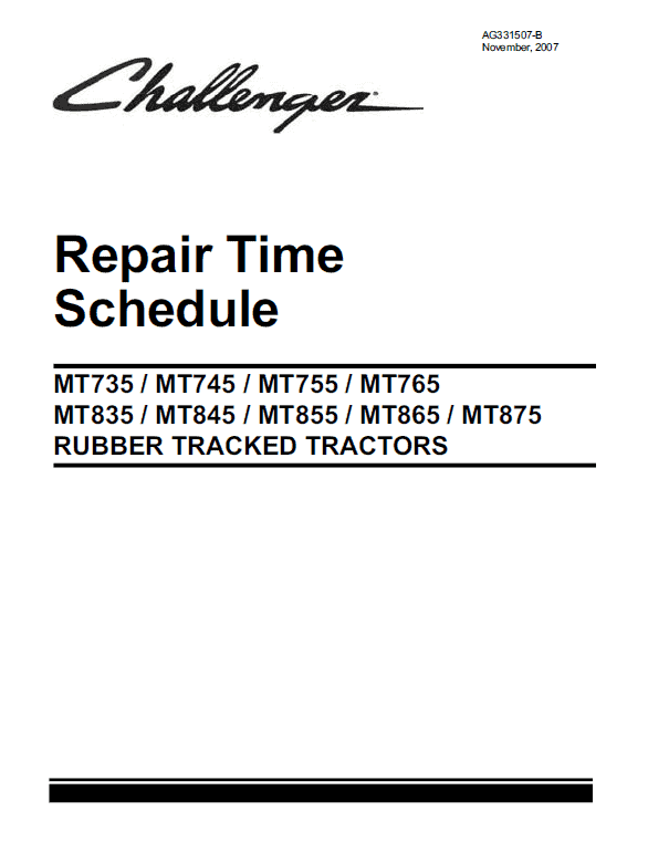
Challenger MT735, MT745, MT755, MT765 Tractor Repair Schedule Manual : 716 Pages
Format: PDF
Book Number: 79023971 & AG331507-B
English
Issued October 2005
Description
Challenger MT735, MT745, MT755, MT765 Tractor Service Manual
Manual for:
AGCO Challenger
MT700 Series Tractor
Format: PDF
Book Number: 79023971 & AG331507-B
English
Issued October 2005
Challenger MT735, MT745, MT755, MT765 Tractor Workshop Manual : 2771 Pages
Challenger MT735, MT745, MT755, MT765 Tractor Repair Schedule Manual : 716 Pages
MT700 Series Manual TABLE OF CONTENTS
INTRODUCTION …………………………………………………………………………………………………………………………………………… 01 A
ENGINE ……………………………………………………………………………………………………………………………………………………….. 02A
ENGINE AUXILIARY ……………………………………………………………………………………………………………………………………… 028
POWERTRAIN SYSTEM OPERATION …………………………………………………………………………………………………………… 03A
POWERTRAIN DISASSEMBLY AND ASSEMBLY …………………………………………………………………………………………… 038
STEERING AND BRAKE SYSTEM ………………………………………………………………………………………………………………… 04A
UNDERCARRIAGE ……………………………………………………………………………………………………………………………………….. OSA
HYDRAULIC AND THREE POINT HITCH lESTING AND ADJUSTING …………………………………………………………….. 06A
HYDRAULIC SCHEMATICS ………………………………………………………………………………………………………………………….. 068
ELECTRICAL SCHEMATICS …………………………………………………………………………………………………………………………. 07A
lRACTOR MANAGEMENT SYSTEM CENTER (TMC) ……………………………………………………………………………………. OBA
AUTO-GUIDE SYSTEMS OPERATION ………………………………………………………………………………………………………….. 088
CAB HEATING AND AIR CONDITIONING ……………………………………………………………………………………………………… 09A
COMPONENT SPECIFICATIONS ………………………………………………………………………………………………………………….. 1 OA
COMPONENT DISASSEMBLY AND ASSEMBL Y ……………………………………………………………………………………………. 1 OB
lROUBLESHOOTING …………………………………………………………………………………………………………………………………… 11 A
MT735, MT745, MT755, MT765 Manual Extract
The Challenger MT700 Series Tractors are equipped with a hydraulic brake control system, which uses pressurized oil from the implement hydraulic system to engage the service brakes. The implement pump charges an accumulator. The pressurized oil from the accumulator is modulated to the service brakes by the brake control valve.
The pressure that is stored in the brake accumulator will permit full braking power even when the implement hydraulic system is not in operation. A fully charged brake accumulator will provide four to six full applications of the service brakes before the accumulator will need to be recharged.
Priority Valve
FIG. 119: The priority valve (1) is located on the left side of the tractor next to the hydraulic oil filter for the implement hydraulic system.
The priority valve will direct hydraulic oil flow to the brake valve in order to recharge the brake accumulator when the brake accumulator pressure drops below a preset level.
When the hydraulic control valve bank is using full hydraulic flow from the implement pump and the brake accumulator is recharging, the brake accumulator will receive priority over the hydraulic control valve bank.
While the accumulator is being recharged, hydraulic oil flow to the hydraulic control valve bank will be reduced for a very short time. This reduction in pressure and flow should not noticeably affect the operation of hydraulic devices that are attached to the hydraulic control valve bank. A slight drop in hydraulic pressure and flow may occur in the hydraulic control valve bank.
v
Share


