1
/
of
4
Uploader
Doosan DX140LC-3 and DX140LC-5 Excavator Service Manual Workshop Guide
Doosan DX140LC-3 and DX140LC-5 Excavator Service Manual Workshop Guide
Regular price
$35.50 USD
Regular price
Sale price
$35.50 USD
Unit price
/
per
Taxes included.
Shipping calculated at checkout.
Couldn't load pickup availability
Manual Included:
Shop Manual:
900 Pages and 1504 Pages
Specifications:
Brand:
Doosan Excavator
Model:
DX140LC-3 and DX140LC-5
Serial Number:
1001 and Up
Type:
Excavator
Manuals:
Shop Manual
Publication Number:
950106-00388E (April 2012) and 950106-01141E (Feb 2015)
Language:
English
Format:
PDF
Description
Table of Contents:-
Safety
Track Excavator Maintenance Safety …………………………………………… SP002322
Specifications
Specifications for DX140LC-3……………………………………………………… SP002509
General Maintenance
General Maintenance Instructions……………………………………………….. SP002454
Standard Torques……………………………………………………………………… SP002404
Upper Structure
Cabin ………………………………………………………………………………………. SP002324
Counterweight…………………………………………………………………………… SP002510
Fuel Tank…………………………………………………………………………………. SP002511
Fuel Transfer Pump (Option) ………………………………………………………. SP002546
Swing Bearing…………………………………………………………………………… SP002329
Swing Reduction Gear……………………………………………………………….. SP002526
Lower Structure and Chassis
Track Assembly ………………………………………………………………………… SP002512
Engine and Drivetrain
Engine Coolant Heater (Option) ………………………………………………….. SP002328
Drive Coupling (Main Pump)……………………………………………………….. SP002515
Hydraulics
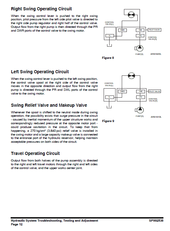
Hydraulic System Troubleshooting, Testing and Adjustment …………… SP002538
Accumulator……………………………………………………………………………… SP002455
Center Joint (Swivel)………………………………………………………………….. SP002456
Cylinders………………………………………………………………………………….. SP002539
Swing Motor……………………………………………………………………………… SP002527
Travel Device……………………………………………………………………………. SP002516
Main Pump……………………………………………………………………………….. SP002517
Gear Pump ………………………………………………………………………………. SP002500
Main Control Valve ……………………………………………………………………. SP002528
Remote Control Valve (Work Lever / Joystick) ………………………………. SP002395
Travel Control Valve (with Damper)……………………………………………… SP002381
Solenoid Valve Assembly …………………………………………………………… SP002406
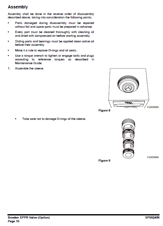
Breaker EPPR Valve (Option) …………………………………………………….. SP002458
Dozer Valve ……………………………………………………………………………… SP002529
Hydraulic Schematic (DX140LC-3& DX140LC-5)…………………………. SP002518
Electrical System
Electrical System ………………………………………………………………………. SP002337
Electrical Schematic ………………………………………………………………….. SP002508
Attachments
Boom and Arm………………………………………………………………………….. SP002513
Bucket……………………………………………………………………………………… SP002506
Doosan DX140LC-3 and DX140LC-5 Manual Instruction Extract:
Fuel Injectors
Overview
NOTE: If a replacement electronic unit injector is installed, the correct injector code must be programmed into the electronic control module. The code that is required is located at position (X). Record code (X) before the electronic unit injector is installed.
The fuel injectors contain no serviceable parts apart from the O-ring seal and the combustion washer. The clamp and setscrew are serviced separately. The pressurized fuel from the fuel manifold is injected into the combustion chamber by the electronic unit injector. The desired injection timing, injection quantity and injection pattern are controlled by the ECM depending on engine operating conditions.
The injection process is controlled using a two-way valve. The supply of electrical current to the solenoid controls the two-way valve. When the two-way valveis not energized the out orifice is closed and there is no fuel leak. In this condition the pressure in the control chamber and the pressure at the nozzle needle are the same. In this condition the spring pressure on the command piston keeps the needle closed.
When an injection of fuel is required, the electrical current from the ECM charges the solenoid, which in turn energizes the two-way valve and lifts the valve.
When the valve lifts the valve uncovers the out orifice. The fuel starts to flow and reduces the pressure in the control chamber. When the pressure difference at the nozzle needle exceeds the combined pressure of the control chamber pressure and the spring pressure, the nozzle lifts to start the injection process. The fuel coming out of the nozzle is atomized and injected as a very fine spray.
When the injection needs to be stopped the electrical current to the solenoid is cut off and the pressure difference in the control chamber starts increasing. The increased pressure difference stops the injection process when the combined pressure exceeds the nozzle pressure.
The electronic unit injectors can be instructed to inject fuel multiple times during the combustion process.
A close pilot injection occurs before the main injection.
The close pilot injection helps to reduce NOx and noise. The main injection period helps to increase the torque of the engine. The after injection period helps to reduce the amount of smoke that is produced.
How to Use The Doosan DX140LC-3 and DX140LC-5 Excavator Guide Manual:
This manual provides information for servicing the DX140LC-3 and DX140LC-5 Doosan Excavator. All service procedures are broken down into detailed steps, listed in their recommended sequence. The manual uses both photographs and drawings to help locate and itemize components. The table of Contents on the preceding pages is your best tool for finding the service procedure you need. Be certain to observe all Safety information included in these pages.
A schematic of each of the major engine systems is provided at the beginning of the section of the manual devoted to troubleshooting and repairing that particular system.
Basic safety precautions are list in the Safety section of the Doosan DX140LC-3 and DX140LC-5 Excavator Service Manual. Additional safety precautions are list in the Safety section of the owner/operation/maintenance publication. Specific safety warnings for all these publications are provided in the description of operations where hazards exist. WARNING labels have also been put on the product to provide instructions and to identify specific hazards.
Share