1
/
of
4
Uploader
Doosan DX15 and DX18 Excavator Service Manual Workshop Guide
Doosan DX15 and DX18 Excavator Service Manual Workshop Guide
Regular price
$33.00 USD
Regular price
Sale price
$33.00 USD
Unit price
/
per
Taxes included.
Shipping calculated at checkout.
Couldn't load pickup availability
Manual Included:
Service Repair Manual:
513 Pages
Specifications:
Brand:
Doosan Daewoo
Model:
DX15 and DX18
Serial Number:
4001 and Up
Type:
Excavator
Manuals:
Service Repair Manual
Publication Number:
K1043970AE
Language:
English
Format:
PDF
Description
How to Use The Doosan DX15 and DX18 Excavator Guide Manual:
This manual provides information for servicing the DX15 and DX18 Doosan Excavator. All service procedures are broken down into detailed steps, listed in their recommended sequence. The manual uses both photographs and drawings to help locate and itemize components. The table of Contents on the preceding pages is your best tool for finding the service procedure you need. Be certain to observe all Safety information included in these pages.
A schematic of each of the major engine systems is provided at the beginning of the section of the manual devoted to troubleshooting and repairing that particular system.
Basic safety precautions are list in the Safety section of the Doosan DX15 and DX18 Excavator Service Manual. Additional safety precautions are list in the Safety section of the owner/operation/maintenance publication. Specific safety warnings for all these publications are provided in the description of operations where hazards exist. WARNING labels have also been put on the product to provide instructions and to identify specific hazards.
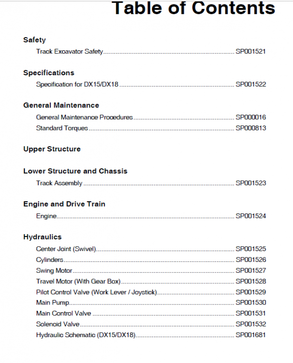
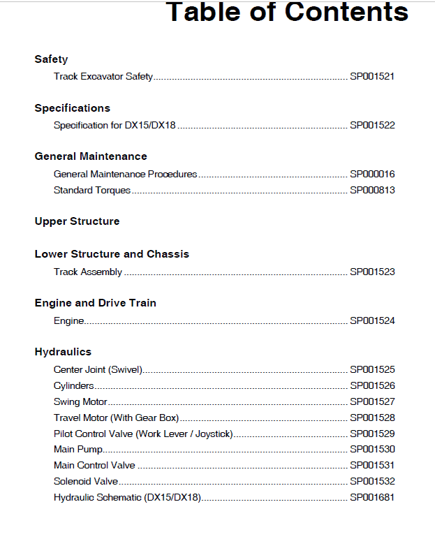
Table of Contents :-
Safety
Track Excavator Safety………………………………………………………………. SP001521
Specifications
Specification for DX15/DX18 ………………………………………………………. SP001522
General Maintenance
General Maintenance Procedures……………………………………………….. SP000016
Standard Torques……………………………………………………………………… SP000813
Upper Structure
Lower Structure and Chassis
Track Assembly ………………………………………………………………………… SP001523
Engine and Drive Train
Engine……………………………………………………………………………………… SP001524
Hydraulics
Center Joint (Swivel)………………………………………………………………….. SP001525
Cylinders………………………………………………………………………………….. SP001526
Swing Motor……………………………………………………………………………… SP001527
Travel Motor (With Gear Box)……………………………………………………… SP001528
Pilot Control Valve (Work Lever / Joystick)……………………………………. SP001529
Main Pump……………………………………………………………………………….. SP001530
Main Control Valve ……………………………………………………………………. SP001531
Solenoid Valve………………………………………………………………………….. SP001532
Hydraulic Schematic (DX15/DX18)………………………………………………. SP001681
Electrical System
Electrical System………………………………………………………………………. SP001534
Electrical Schematic (DX15/DX18) ………………………………………………. SP001535
Attachments
Boom and Arm………………………………………………………………………….. SP001536
Bucket……………………………………………………………………………………… SP001550
Manual Instruction Extract:
Removal of Valves Camshaft
1. When it is necessary to remove only valve camshaft, use
following procedure:
A. Dismount cylinder head assembly.
B. Pull out push rods.
C. Pull out tappets.
D. Remove gear case assembly.
E. Remove camshaft stopper bolt.
F. Draw camshaft assembly out.
2. Removal of injection pump camshaft.
A. Disconnect injection pipes.
B. Remove injection pump assembly.
C. Remove rear case assembly.
D. Remove shaft rear cover.
E. Remove stopper bolt.
F. Pull out shaft to front side.
Share