1
/
of
4
Uploader
Doosan DX340LC-5 and DX350LC-5 Excavator Service Manual Workshop Guide
Doosan DX340LC-5 and DX350LC-5 Excavator Service Manual Workshop Guide
Regular price
$36.00 USD
Regular price
Sale price
$36.00 USD
Unit price
/
per
Taxes included.
Shipping calculated at checkout.
Couldn't load pickup availability
Manual Included:
Shop Manual:
1631 Pages
Specifications:
Brand:
Doosan
Model:
DX340LC-5, DX350LC-5
Serial Number:
10001 and Up
Type:
Excavator
Manuals:
Shop Manual
Publication Numbers:
950106-01001E (Apr 2014)
Language:
English
Format:
PDF
Description
Table of Contents
Track Excavator Maintenance Safety
Specifications
General Maintenance Instructions
Standard Torques
Engine
Engine Coolant Heater (Option)
Cabin
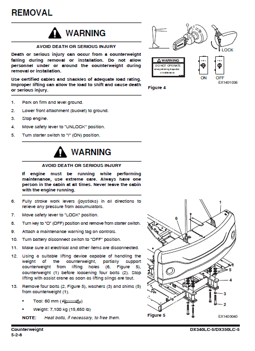
Counterweight
Hydraulic Oil Tank
Fuel Tank
Main Pump
Drive Coupling (Main Pump)
Main Control Valve
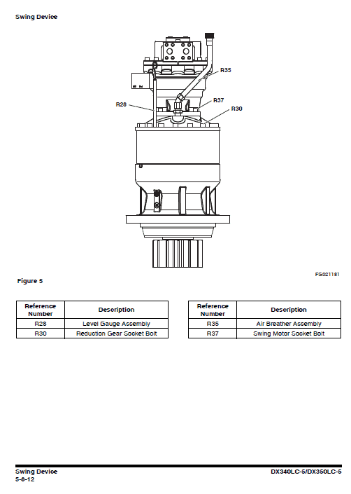
Swing Device
Fan Pump for Oil Cooler
Fan Motor for Oil Cooler
Gear Pump (Rotation)
Joystick Valve (Work Lever)
Travel Control Valve (with Damper)
Solenoid Valve
Accumulator
Two Pump
Swing Bearing
Center Joint
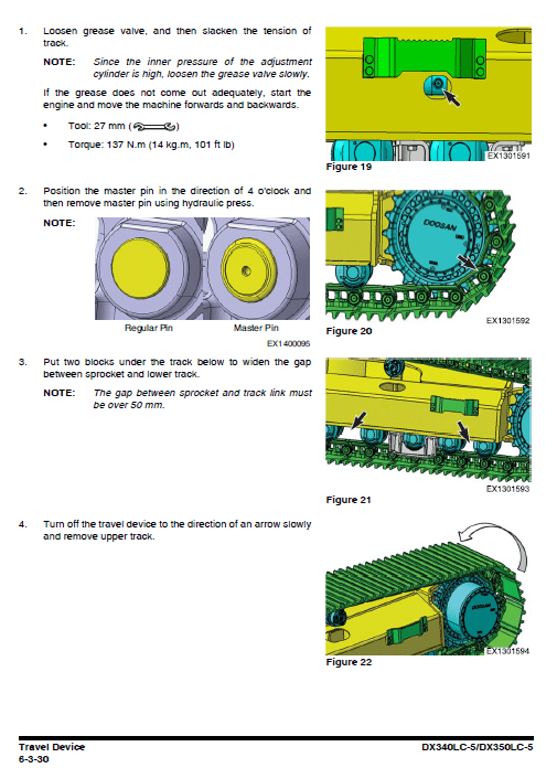
Travel Device
Track Assembly
How to Use The Guide Manual
This manual provides information for servicing the Excavator. All service procedures are broken down into detailed steps, listed in their recommended sequence. The manual uses both photographs and drawings to help locate and itemize components. The table of Contents on the preceding pages is your best tool for finding the service procedure you need. Be certain to observe all Safety information included in these pages.
A schematic of each of the major engine systems is provided at the beginning of the section of the manual devoted to troubleshooting and repairing that particular system.
Basic safety precautions are list in the Safety section of the Service Manual. Additional safety precautions are list in the Safety section of the owner/operation/maintenance publication. Specific safety warnings for all these publications are provided in the description of operations where hazards exist. WARNING labels have also been put on the product to provide instructions and to identify specific hazards.
Instruction Extract:
Power Take-off
Procedure
To seal the cover of the power take-off.
1. Remove two attaching screws (2) of the cover (1) with an Allen key (WAF 10).
2. Turn the cover 45 and pull off the cover.
3. Remove old O-ring (3) and replace it with a new one.
Inspect the case and the groove.
4. Insert the new O-ring in the recess in the cover and install the cover.
5. Tighten the attaching screws (2) according to the specifications in chapter
Precaution on page 41.
Share


