1
/
of
4
Uploader
Hino 145, 165, 185, 238, 268, 338 Series Year 2005 Repair Manual Workshop Guide
Hino 145, 165, 185, 238, 268, 338 Series Year 2005 Repair Manual Workshop Guide
Regular price
$36.00 USD
Regular price
Sale price
$36.00 USD
Unit price
/
per
Taxes included.
Shipping calculated at checkout.
Couldn't load pickup availability
This is the Repair and Service Manual for
Hino Truck
2005
Series: 145 (NA6J), 165 (NB6J), 185 (NC6J), 238 (ND8J), 268 (NE8J, NJ8J) and 338 (NV8J)
Equipped with J05D-TA, J08E-TA and J08E-TB engine
Format: PDF
Language: English
Hino 2005 Truck 145, 165, 185, 238, 268 and 338 Series Manual – 1376 Pages
Hino 2005 Truck Owners Manual – 266 Pages
Hino J08E-TA and J08E-TB Engine Manual – 351 Pages
Hino J05D-TA Engine Manual – 324 Pages
Description
Hino 145, 165, 185, 238, 268, 338 Series Year 2005 Repair Manual
This is the Repair and Service Manual for
Hino Truck
2005
Series: 145 (NA6J), 165 (NB6J), 185 (NC6J), 238 (ND8J), 268 (NE8J, NJ8J) and 338 (NV8J)
Equipped with J05D-TA, J08E-TA and J08E-TB engine
Format: PDF
Language: English
Hino 2005 Truck 145, 165, 185, 238, 268 and 338 Series Manual – 1376 Pages
Hino 2005 Truck Owners Manual – 266 Pages
Hino J08E-TA and J08E-TB Engine Manual – 351 Pages
Hino J05D-TA Engine Manual – 324 Pages
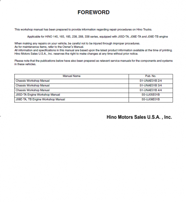
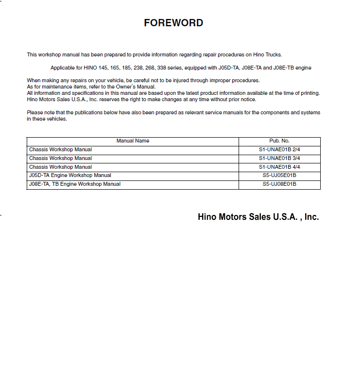
This workshop manual has been prepared to provide information covering repairs on 145, 165, 185, 238, 268 and 338 series Hino 2005 trucks.
To use Hino 2005 trucks for years, smoothly, safely, and economically without trouble, it is important to perform inspections.
Maintenance required to be performed is the responsibility of the owner. Some recommended repairs of your truck are mentioned. When making any repair of your truck, be careful not to be injured through improper procedures.
As for maintenance items, refer to the Owners and Drivers Manual. All information and specifications in this manual are based upon the latest product information available at the time of printing.
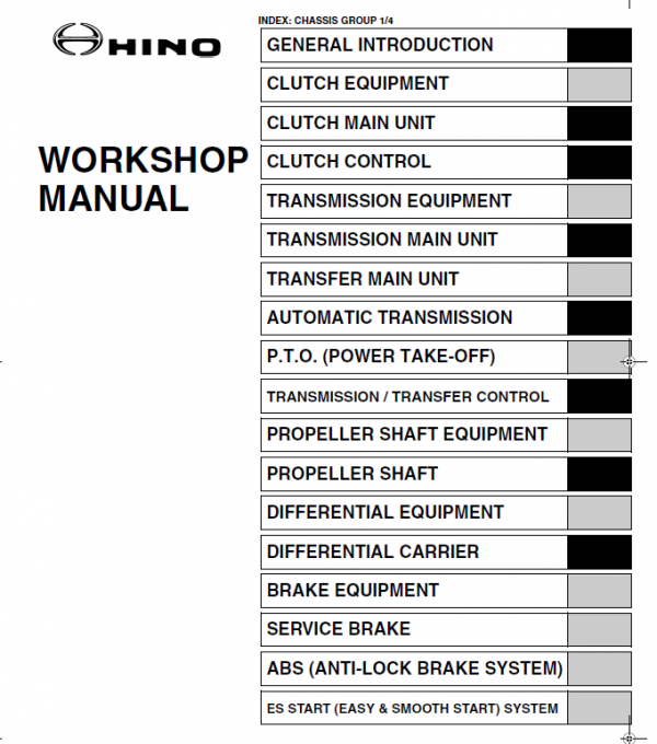
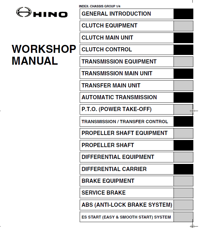
Table of Content For Hino 2005 Truck Manual:
General Introduction
Clutch Equipment
Clutch Main Unit
Clutch Control
Transmission Equipment
Transmission Main Unit
Transfer Main Unit
Automatic Transmission
P.t.o. (Power Take-off)
Transmission / Transfer Control
Propeller Shaft
Differential Equipment
Differential Carrier
Index: Chassis Group 1/4
Propeller Shaft Equipment
Workshop
Manual
Brake Equipment
Service Brake
Abs (Anti-lock Brake System)
Es Start (Easy & Smooth Start) System
Exhaust Brake
Retarder Brake
Parking Brake
Steering Equipment
Steering Unit
Power Steering
Index: Chassis Group 2/4
Axle Equipment
Front Axle
Rear Axle
Wheel & Tire
Suspension Equipment
Suspension
Chassis Equipment
Chassis Frame
Coupler (5th Wheel)
Pintle Hook
Cab Equipment
Cab
Electrical Equipment
Electric Wire
Hino Truck 2005 Manual Instruction Extract:
How to Assemble the the FSO-6406/8406 Shift Bar Housing Special Instructions
Interlock balls, detent balls, and springs can be used interchangeably.
Lubricate yoke pads and inserts with oil before assembly.
Lubricate yoke bar grooves with grease before assembly.
Keep yoke bars in neutral while assembling.
The shift yoke retainer holes are not tapped on new shift bar housings. The capscrews that are used are thread forming and can be reused if the shift bar housing is replaced.
It may be necessary to support the yoke bars in position while installing the retainers.
1. Install interlock balls, detent balls and springs in the following sequence;
A. Position (3) balls in the reverse light switch bore.
B. Install reverse detent spring and ball.
C. Position (2) balls in adjacent cross bore.
D. Repeat steps B and C for 1st-2nd position, 3rd-4th position, and 5th-6th position.
NOTE: Balls and springs can be used interchangeably.
2. Position reverse yoke in housing assembly as shown.
3. Install the interlock pin in 1st-2nd yoke assembly.
4. Position 1st-2nd yoke in housing assembly.
5. Install the interlock pin in 3rd-4th yoke assembly.
6. Position 3rd-4th yoke in housing assembly.
7. Position 5th-6th shift block in housing assembly.
8. Install the middle retainer capscrews.
NOTE: It may be necessary to support rails in proper position while installing retainer.
•
Share