1
/
of
4
Uploader
Hino Truck FA4J, FB4J Year 2004 Repair Manual (FA, FB) Workshop Guide
Hino Truck FA4J, FB4J Year 2004 Repair Manual (FA, FB) Workshop Guide
Regular price
$35.00 USD
Regular price
Sale price
$35.00 USD
Unit price
/
per
Taxes included.
Shipping calculated at checkout.
Couldn't load pickup availability
This is the Repair and Service Manual for
Hino Truck
2004
Series: FA, FB, FD, FE and SG
Format: PDF
Language: English
Hino 2004 Truck FA and FB Series Manual – 1104 Pages
Description
Hino Truck FA4J, FB4J Year 2004 Repair Manual (FA, FB)
This is the Repair and Service Manual for
Hino Truck
2004
Series: FA, FB, FD, FE and SG
Format: PDF
Language: English
Hino 2004 Truck FA and FB Series Manual – 1104 Pages
This workshop manual has been prepared to provide information covering repairs on FA, FB series Hino 2004 trucks.
To use Hino 2004 trucks for years, smoothly, safely, and economically without trouble, it is important to perform inspections.
Maintenance required to be performed is the responsibility of the owner. Some recommended repairs of your truck are mentioned. When making any repair of your truck, be careful not to be injured through improper procedures.
As for maintenance items, refer to the Owners and Drivers Manual. All information and specifications in this manual are based upon the latest product information available at the time of printing.
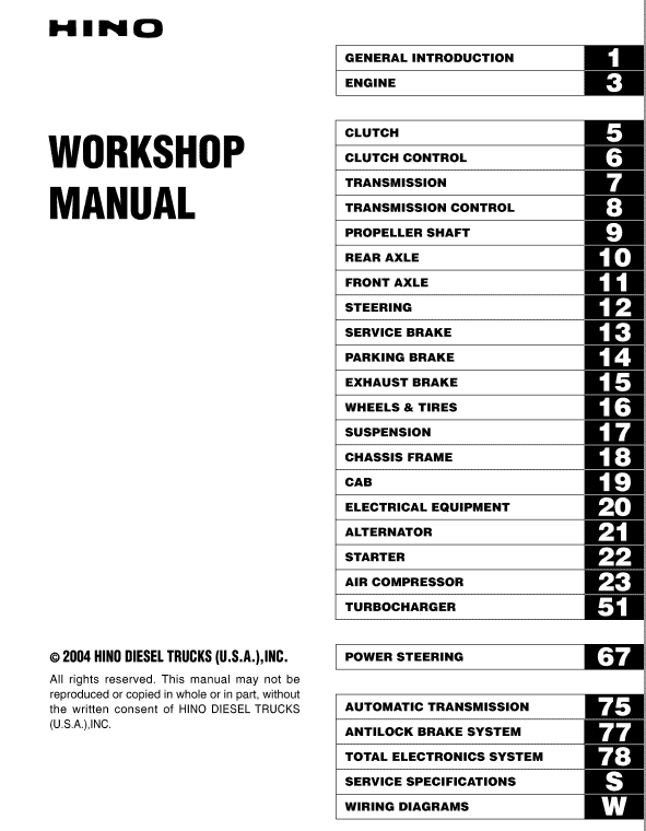
Table of Content For Hino 2004 Truck Manual:
General Introduction
Engine
Clutch
Clutch Control
Transmission
Transmission Control
Propeller Shaft
Rear Axle
Front Axle
Steering
Service Brake
Parking Brake
Exhaust Brake
Wheels & Tires
Suspension
Chassis Frame
Cab
Electrical Equipment
Alternator
Starter
Compressor
Turbocharger
Spring Brake
Power Steering
Automatic Transmission
Antilock Brake System
Total Electronics System
Service Specification
Electrical Wiring Diagrams
Hino Truck 2004 Manual Instruction Extract:INSPECTION
1. CHECK THE OPERATION OF THE ENGINE STOP MOTOR AND MECHANICAL
SWITCH.
WARNING
When the engine stop cover is removed, do not touch the cable or pulley with your hands, even when the key switch is in the "ACC" or "OFF" (LOCK) positions.
Check the motor only after removing the connector to the battery to avoid injury to your hands.
1. Devise a circuit as shown in Fig. 8.
2. Turn the switch on to rotate the motor. Then confirm that the motor stops at the point where the cable spring moves to the "in use" position.
3. The motor and the mechanical switch are both operating normally if when the switch is turned off, the motor rotates and stops at the point where the cable spring moves to the "stop" position.
2. IF THE ENGINE DOES NOT STOP WHEN THE STARTER SWITCH IS IN THE "OFF" POSITION, DO THE FOLLOWING.
1. Turn the starter switch to the "ON" position.
2. Open the front panel.
3. Disconnect the engine stop motor connector.
4. Remove the engine stop motor cover.
5. Pull the engine stop cable in the direction of the arrow until the engine stops.
6. When the engine stops re-install the engine stop motor cover.
7. Reconnect the engine stop motor connector.
8. Put the starter switch in the "LOCK" position.
Share


