1
/
of
4
Uploader
Komatsu HM300-1L Dump Truck Service Manual Workshop Guide
Komatsu HM300-1L Dump Truck Service Manual Workshop Guide
Regular price
$35.00 USD
Regular price
Sale price
$35.00 USD
Unit price
/
per
Taxes included.
Shipping calculated at checkout.
Couldn't load pickup availability
Manual Included:
Shop Manual:
1256 pages (CEBM015200)
Operation and Maintenance Manual:
254 pages (CEAM015401)
Specifications:
Brand:
Komatsu
Model:
HM300-1L
Serial Number:
A10001 and up
Type:
Dump Truck
Manuals:
Shop Manual and Operation and Maintenance Manual
Publication Number:
CEBM015200 and CEAM015401
Language:
English
Format:
PDF
Description
Table of Contents
01 GENERAL . . . . . . . . . . . . . . . . . . . . . . . . . . . . . . . . . . . . . . . . . . . . . . . . . . . . . . . . . . . . . 01-1
10 STRUCTURE AND FUNCTION. . . . . . . . . . . . . . . . . . . . . . . . . . . . . . . . . . . . . . . . . . . . . 10-1
20 TESTING, ADJUSTING AND TROUBLESHOOTING . . . . . . . . . . . . . . . . . . . . . . . . . . . . 20-1
30 DISASSEMBLY AND ASSEMBLY. . . . . . . . . . . . . . . . . . . . . . . . . . . . . . . . . . . . . . . . . . . 30-1
90 DIAGRAMS AND SCHEMATICS. . . . . . . . . . . . . . . . . . . . . . . . . . . . . . . . . . . . . . . . . . . . 90-1
GENERAL
This section lists the general machine dimensions, performance specifications, component weights, and fuel, coolant and lubricant specification charts.
STRUCTURE, FUNCTION AND MAINTENANCE STANDARD
This section explains the structure and function of each component. It serves not only to give an understanding of the structure, but also serves as reference material for troubleshooting.
TESTING, ADJUSTING AND TROUBLESHOOTING KOMATSU Dump Truck HM300-1L
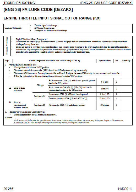
This section explains checks to be made before and after performing repairs, as well as adjustments to be made at completion of the checks and repairs. Troubleshooting charts correlating Problems to Causes are also mention in this section.
DISASSEMBLY AND ASSEMBLY
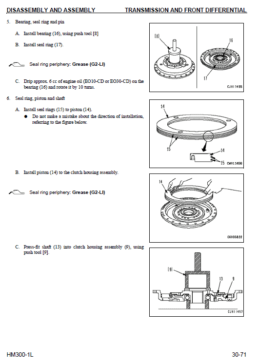
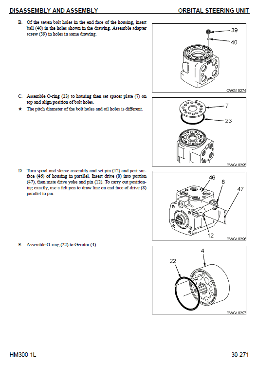
This section explains the order to be followed when removing, installing, disassembling or assembling each component, as well as precautions to be taken for these operations.
TRUCK BODY ASSEMBLY REMOVAL
1. Remove both hoist cylinder rod pins (1).
• Sling the bottom of the hoist cylinder temporarily.
• After removing pin (1) from each cylinder rod, install lever block 1 between the vehicle body and hoist cylinder and tense it to prevent the hoist cylinder from falling down.
2. Loosening lever block B, lower the crane to place the bottom of the hoist cylinder on the tire.
A. Place block C between the bottom of the hoist cylinder and tire.
B. Install lever block B between the vehicle body and hoist cylinder and tense it to prevent the hoist cylinder from falling down.
3. Sling the body temporarily.
4. Disconnect body potentiometer linkage (2) from the body.
5. Remove body hinge pins (3) on both sides.
6. Lift off body assembly (4).
WARNING! If rod pin (1) is removed, the hoist cylinder falls outward. Accordingly, be sure to pull the cylinder toward inside of the vehicle body in advance.
Body assembly: 4450 kg (9,811 lbs)
Share


