1
/
of
4
Uploader
Komatsu PC228US-3 and PC228USLC-3 Excavator Service Manual Workshop Guide
Komatsu PC228US-3 and PC228USLC-3 Excavator Service Manual Workshop Guide
Regular price
$34.00 USD
Regular price
Sale price
$34.00 USD
Unit price
/
per
Taxes included.
Shipping calculated at checkout.
Couldn't load pickup availability
Manual Included:
Shop Manual:
598 pages and 672 pages
Specifications:
Brand:
Komatsu
Model:
PC228US-3, PC228USLC-3
Type:
Excavator
Serial Numbers:
20001 and up
30001 and up
Manuals:
Shop Manual
Publication Number:
SEBM023104 and SEBM030506
Language:
English
Format:
PDF
Description
Table of Contents
01 GENERAL . . . . . . . . . . . . . . . . . . . . . . . . . . . . . . . . . . . . . . . . . . . . . . . . . . . . . . . . . . . . . 01-1
10 STRUCTURE AND FUNCTION. . . . . . . . . . . . . . . . . . . . . . . . . . . . . . . . . . . . . . . . . . . . . 10-1
20 TESTING, ADJUSTING AND TROUBLESHOOTING . . . . . . . . . . . . . . . . . . . . . . . . . . . . 20-1
30 DISASSEMBLY AND ASSEMBLY. . . . . . . . . . . . . . . . . . . . . . . . . . . . . . . . . . . . . . . . . . . 30-1
90 OTHER . . . . . . . . . . . . . . . . . . . . . . . . . . . . . . . . . . . . . . . . . . . . . . . . . . . . . . . . . . . . . . . . 90-1
GENERAL
This section lists the general machine dimensions, performance specifications, component weights, and fuel, coolant and lubricant specification charts.
STRUCTURE, FUNCTION AND MAINTENANCE STANDARD
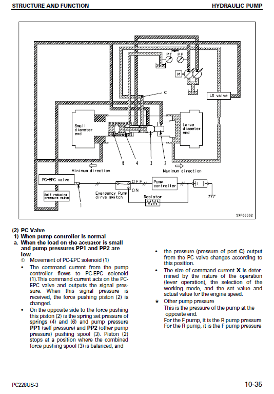
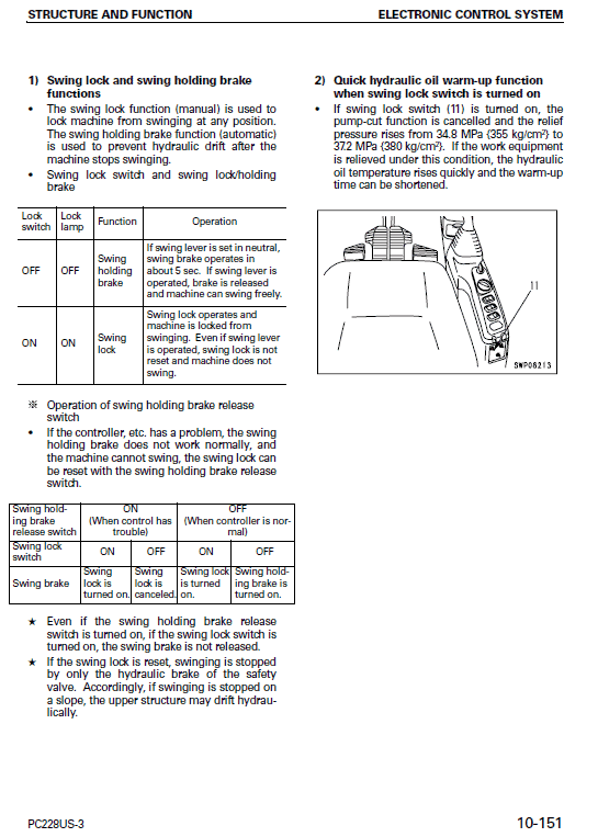
This section explains the structure and function of each component. It serves not only to give an understanding of the structure, but also serves as reference material for troubleshooting.
TESTING, ADJUSTING AND TROUBLESHOOTING
This section explains checks to be made before and after performing repairs, as well as adjustments to be made at completion of the checks and repairs. Troubleshooting charts correlating Problems to Causes are also mention in this section.
DISASSEMBLY AND ASSEMBLY
KOMATSU Excavator PC228US-3 and PC228USLC-3
This section explains the order to be followed when removing, installing, disassembling or assembling each component, as well as precautions to be taken for these operations.
When raising heavy components, use a hoist or crane. Check that the wire rope, chains and hooks are free from damage.
Always use lifting equipment which has ample capacity. Install the lifting equipment at the correct places. Use a hoist or crane and operate slowly to prevent the component from hitting any other part. Do not work with any part still raised by the hoist or crane.
•
MANUAL EXTRACT
TESTING AND ADJUSTING FUEL INJECTION TIMING
1. Testing
1) Remove the engine hood, then remove the counterweight for maintenance at the rear of chassis (engine end).
(For details, see TESTING AND ADJUSTING, Removal and installation of counterweight.) 2) Using cranking tool Q, rotate the crankshaft in the normal direction until timing pin (1) enters the hole in the gear.
3) Remove plug (2), reverse timing pin (3), and check that pin (3) is meshed with timing pin pointer (4) at the injection pump side.
2. Adjusting
• If the timing pin does not mesh i) Remove the fuel injector pump.
For details, see REMOVAL OF FUEL INJECTION PUMP ASSEMBLY.
ii) Rotate the camshaft of the injection pump and mesh timing pin (3) with timing pin pointer (4).
iii) Install the fuel injection pump assembly.
For details, see INSTALLATION OF
Share


