1
/
of
4
Uploader
Komatsu WB140-2 and WB150-2 Backhoe Loader Service Manual Workshop Guide
Komatsu WB140-2 and WB150-2 Backhoe Loader Service Manual Workshop Guide
Regular price
$34.00 USD
Regular price
Sale price
$34.00 USD
Unit price
/
per
Taxes included.
Shipping calculated at checkout.
Couldn't load pickup availability
Manual Included:
Shop Manual:
474 pages
Specifications:
Brand:
Komatsu
Model:
WB140-2N, WB150-2N
Serial Numbers :
A20001 and up, A60001 and up
Type:
Backhoe Loader
Publication Numbers:
CEBM009802
Manuals:
Shop Manual
Language:
English
Format:
PDF
Description
Table of Contents
10 STRUCTURE AND FUNCTION……………………………………………………………………………. 10-1
20 TESTING AND ADJUSTING ……………………………………………………………………………….. 20-1
30 DISASSEMBLY AND ASSEMBLY………………………………………………………………………. 30-1
40 MAINTENANCE STANDARD………………………………………………………………………………. 40-1
1. General Instructions
This section presents under one heading the basic information and procedures common to the sections on "Disassembly and Assembly", "Testing and Adjustments", "Troubleshooting", and "Removal and Installation". It is essential for the serviceman to thoroughly understand and know this section till it becomes a part of his common sense.
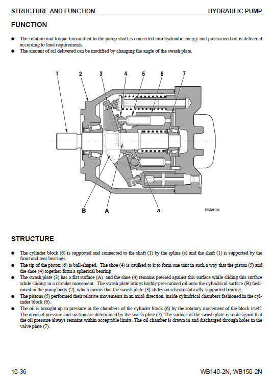
2. Structure and Function
This section gives a detailed explanation of the "Structure" with details and drawings of the "Constituent Parts" and "block" or "circuit" diagrams, arranged for the serviceman, but also useful as a textbook for training service personnel. The Training Aids should is use to cover the basic theory in this manual.
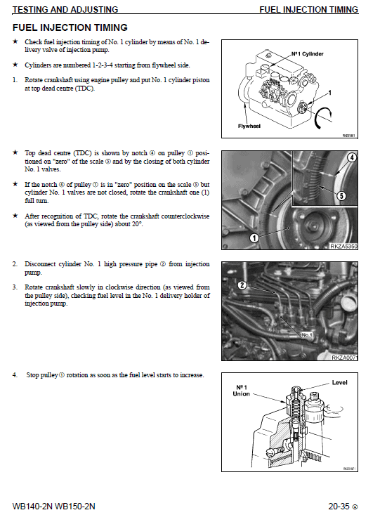
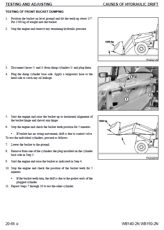
3. Testing and Adjustments
Procedures of all the necessary "Tests" and "Adjustments" are describe with photographs showing the necessary measuring equipment and the location for making the measurements. This should aid the serviceman in his trouble shooting, checking and adjusting work.
4. Troubleshooting
Typical common troubles are listed and systematically described; with their causes and the procedures for finding and diagnosing the symptoms.
As it is impossible to list all of the possible troubles, the serviceman should study the sections covering the "Structure and Function" and "Testing and Adjustments" and apply this knowledge to diagnose any non-listed troubles.
5. Specifications
In this section, all standard dimensions and tolerances that are necessary to perform Testing and Adjustments is mention with drawings together with, appropriate procedures for disassembly and assembly, performing repairs, or troubleshooting. However, basic dimensions and tolerances, for repairs or rebuilding, are limited to those machine parts most commonly worked on.
REMOVAL OF STEERING UNIT
Lower the working equipment completely until it rests on the ground and stop the engine and remove the ignition wrench.
Release all residual pressure in all circuits.
(For details, see 20. TESTING AND ADJUSTMENTS ).
Cut off the supply of electricity by turning the accumulator disconnecting switch in a counter-clockwise direction, and remove the handle.
1 – Disconnect the five pipes (2) from the steering unit (1) and plug them to prevent entry of impurities. Mark the positions to prevent exchanges during re connection.
2 – Remove the central guard (3) beneath the steering wheel.
3 – Raise the protective sleeve (4) and disconnect the connectors (5) and (6).
4 – Disconnect the connector (7) and the relay (8).
5 – Loosen the steering column (10) and the steering unit (1) retaining screws (9) and remove the steering unit.
Share