1
/
of
4
Uploader
Kubota L3240, L3540, L4240, L5040, L5240, L5740 Tractors Service Manual
Kubota L3240, L3540, L4240, L5040, L5240, L5740 Tractors Service Manual
Regular price
$35.00 USD
Regular price
Sale price
$35.00 USD
Unit price
/
per
Taxes included.
Shipping calculated at checkout.
Couldn't load pickup availability
Kubota
Tractor
Model L3240, L3540, L4240, L5040, L5240, L5740
Format: PDF
Publication: 9Y111-01023
Language: English
Kubota L3540, L4240, L5040, L5240, L5740 Tractor Workshop Manual – 666 Pages (Published 2010)
Kubota L3240, L3540, L4240, L5240, L5740 Tractor Workshop Manual – 618 Pages (Published 2011)
Operators (Owners) Manual – 157 Pages
Description
Kubota L3240, L3540, L4240, L5040, L5240, L5740 Tractor Workshop Service Manual
Kubota
Tractor
Model L3240, L3540, L4240, L5040, L5240, L5740
Format: PDF
Publication: 9Y111-01023
Language: English
Kubota L3540, L4240, L5040, L5240, L5740 Tractor Workshop Manual – 666 Pages (Published 2010)
Kubota L3240, L3540, L4240, L5240, L5740 Tractor Workshop Manual – 618 Pages (Published 2011)
Operators (Owners) Manual – 157 Pages
Table of Content of the Workshop Service Manual
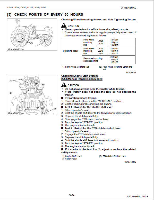
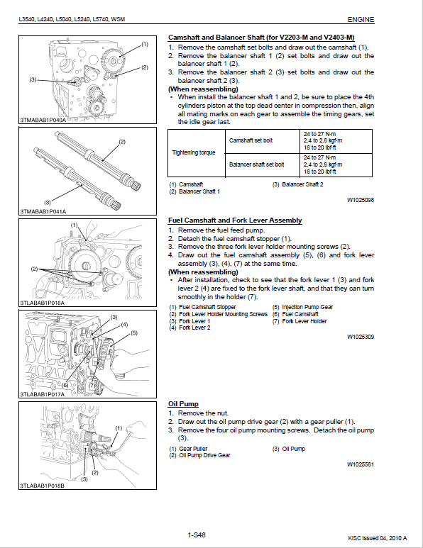
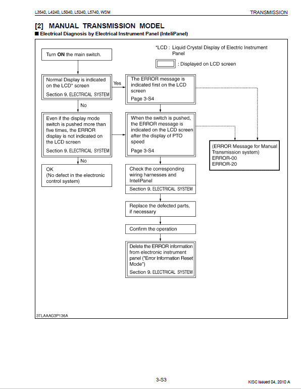
This Workshop Manual has been prepared to provide servicing personnel with information on the mechanism, service and maintenance of KUBOTA Tractor L3240, L3540, L4240, L5040, L5240 and L5740. It is divided into three parts, "General", "Mechanism" and "Servicing" for each section.
– General
Information on the tractor identification, the general precautions, maintenance check list, check and maintenance and special tools are described.
– Mechanism
Information on the construction and function are included. This part should be understood before proceeding with troubleshooting, disassembling and servicing.
Refer to Diesel Engine / Tractor Mechanism Workshop Manual (Code No. 9Y02101874 / 9Y021-18201) for the one which has not been described to this workshop manual.
– Servicing
Information on the troubleshooting, servicing specification lists, tightening torque, checking and adjusting, disassembling and assembling and servicing which cover procedures, precautions, factory specifications and allowable limits.
All information illustrations and specifications contained in this manual are based on the latest product information available at the time of publication.
Manual Extract – PTO Wire and Electric Connector
1. Disconnect the traveling speed sensor connector (1).
2. Disconnect the PTO wire (2) at the PTO clutch valve (4).
3. Remove the coupler support (5) from the stay.
(When reassembling)
• When connecting the PTO wire (2) to the clutch valve (4), be sure to adjust the length of wire as follows.
1. Set the PTO shift lever to OFF (Neutral) position.
2. Loosen the lock nut (3) of wire, and connect wire to the clutch valve lever, and then place the wire to the hook.
3. Tighten the lock nut (3) clockwise (pull the wire), and lock the nut just before the lever moves.
(1) Traveling Speed Sensor Connector
(2) PTO wire
(3) Lock Nut
(4) PTO Clutch Valve
(5) Coupler Support
Share


