1
/
of
4
Uploader
Liebherr L506, L508, L510 Wheel Loader Service Manual
Liebherr L506, L508, L510 Wheel Loader Service Manual
Regular price
$34.00 USD
Regular price
Sale price
$34.00 USD
Unit price
/
per
Taxes included.
Shipping calculated at checkout.
Couldn't load pickup availability
L 506 from serial 101 (Type 371)
L 508 from serial 101 (Type 232 and 372)
L 510 from serial 101 (Type 340)
Language: English
Publication: 8145017
Format: PDF
February 1991
Liebherr L506, L508, L510 Wheel Loader Service Manual – 550 Pages
Description
Liebherr L506, L508, L510 Wheel Loader Manual
Wheel Loader
Applicable Model :
L 506 from serial 101 (Type 371)
L 508 from serial 101 (Type 232 and 372)
L 510 from serial 101 (Type 340)
Language: English
Publication: 8145017
Format: PDF
February 1991
Liebherr L506, L508, L510 Wheel Loader Service Manual – 550 Pages
Table of Content of the Service Manual:
General
Special Tools
Lubricants
Technical Data- Inspection Plans
Engine
Travel Hydraulic
Working Hydraulic
Electrical System
Heating, Air conditioning System
Travel Gear
Axles
Steering
Brakes
Main Frame / Cab
Hoist Frame / Accessories
Special Installations
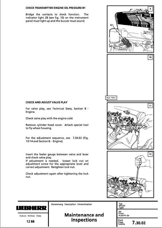
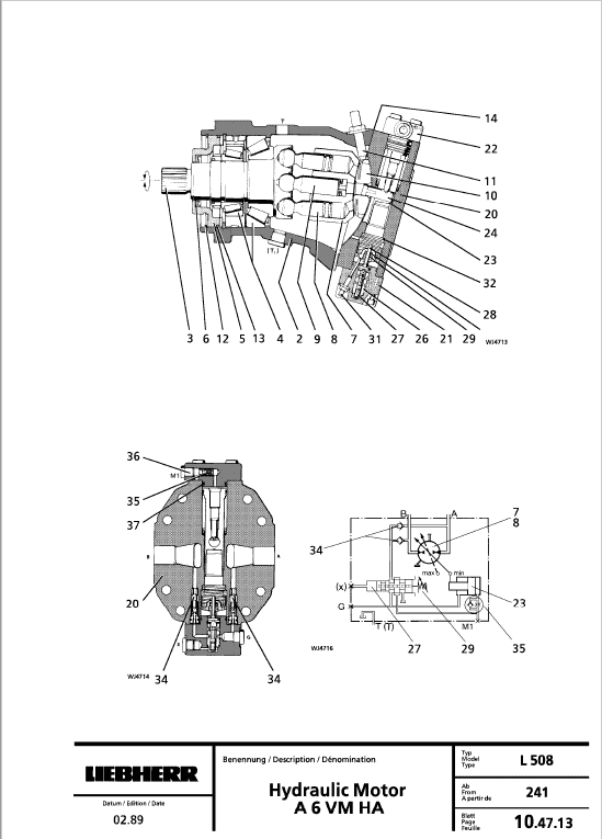
This manual has been issued to provide you with technical information on design, function, disassembly, assembly, adjustments and troubleshooting of components and assemblies on the LIEBHERR wheel loader.
The descriptions are brief but precise, with photographs, drawings, electric and hydraulic circuit schematics and graphic diagrams. This information is intended to simplify any necessary repair work on the LIEBHERR wheel loader.
We deliberately avoided full photographic details of each repair stage, since only skilled mechanics, already familiar with most repair work, should perform these repairs. This manual also contains information about adjustments and adjustment values.
ADJUSTMENT PROCEDURE – CHECKING AND ADJUSTING THE TRAVEL HYDRAULICS
1.1 Please note that during the warranty period only authorized LIEBHERR representatives are permitted to work on the wheel loader valves. This includes adjustment.
1.2 The valves must be checked and adjusted with the hydraulic oil at operating temperature of 60° + 10°C (140° F).
1.3 Use glycerine filled pressure gauges with an accuracy of ± 1 % . 1.4 If specified values cannot be reached, the cause must be determined according to the troubleshooting chart, and the defect must be repaired.
1.5 To check and adjust the following valves, check if the inching device on regulator valve 32 is in neutral position. See section 10.72.
1.6 After the valves have been adjusted, install new safety caps. This will prevent unauthorized personnel from attempting to adjust the valves.
Share


