1
/
of
4
Uploader
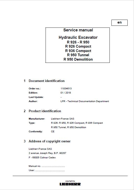
Liebherr R926, R936, R946, R950 Tier 4F Hydraulic Excavator Service Manual
Liebherr R926, R936, R946, R950 Tier 4F Hydraulic Excavator Service Manual
Regular price
$35.00 USD
Regular price
Sale price
$35.00 USD
Unit price
/
per
Taxes included.
Shipping calculated at checkout.
Couldn't load pickup availability
R 926 from serial no. 40625
R 936 from serial no. 40312
R 946 from serial no. 40137
R 950 from serial no. 42213
R 926 Compact from serial no. 40625
R936 Compact from serial no. 45440
R 950 Tunnel from serial no. 37539
R 950 Demolition from serial number 43111
Language: English
Publication: 11692893
Format: PDF
January 2018
Liebherr R926, R936, R946, R950 Tier 4F Excavator Service Manual – 2628 Pages
Operator's manual – 324 Pages
Description
Liebherr R926, R936, R946, R950 Tier 4F Hydraulic Excavator Service Manual
Excavator
Model :
R 926 from serial no. 40625
R 936 from serial no. 40312
R 946 from serial no. 40137
R 950 from serial no. 42213
R 926 Compact from serial no. 40625
R936 Compact from serial no. 45440
R 950 Tunnel from serial no. 37539
R 950 Demolition from serial number 43111
Language: English
Publication: 11692893
Format: PDF
January 2018
Liebherr R926, R936, R946, R950 Tier 4F Excavator Service Manual – 2628 Pages
Operator's manual – 324 Pages
Table of Content of the Service Manual:
Introduction
Technical data
Maintenance
Drive group
Cooling system
Working hydraulics
Hydraulic components
Steering System
Brake System
Electrical system
Transmission /Travel gearbox
Axles / Drive
Steel components – basic machine
Working attachment
Operator's cab, heating and air conditioning
Lubrication system
Slewing gearbox and slewing ring
Equipment / options
Diagnosis
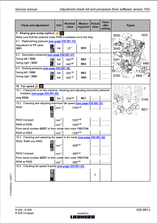
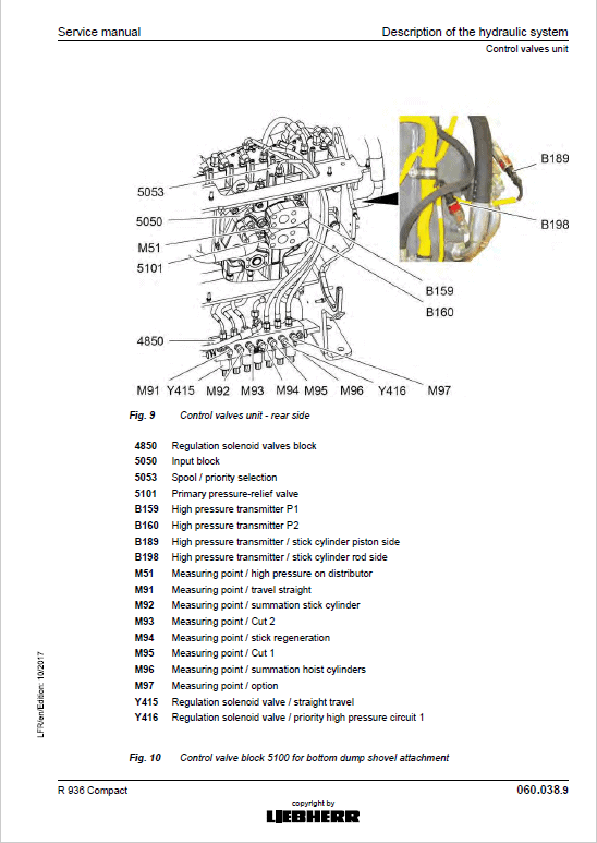
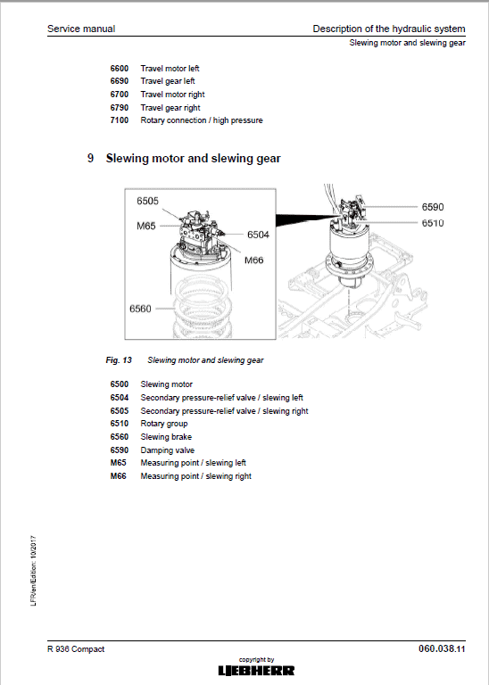
This manual contains technical data, design and functional descriptions as well as instructions for the operation and the adjustment of machine settings. The document includes a number of drawings, functional schematics and detailed views of units and assemblies of Liebherr hydraulic excavators.
Manual Extract – Installing the new chain
Pass the chain under the side frame while pulling it back with a machine.
Pull the chain until two or three links protrude from the middle of the sprocket.
Lower the machine on the rolled off chain.
Jack up the rear end of the chain using a lifting accessory in order to engage the links in the teeth of the sprocket.
Position a wooden wedge 27 to retain the links against the sprocket wheel.
Using a machine or a steel cable fixed to the working attachment, lift and pull the other end of the chain over the guide wheel and the carrier rollers so to make both chain ends join at the rear of the sprocket.
Insert the spacer rings 18 and the end bushing 171 at the end link.
Connect the links using the end bolt 16.
Install the bolt press on the chain end bolt, as necessary, using a lifting accessory.
Press the end bolt 16 in from the outer side of the chain to the inner one.
Remove the bolt press.
Retighten the grease filling nozzle 67 to 170 N.m
Retension the chain, (see 2.3.3 Retensioning a chain page 7).
Share


