1
/
of
4
Uploader
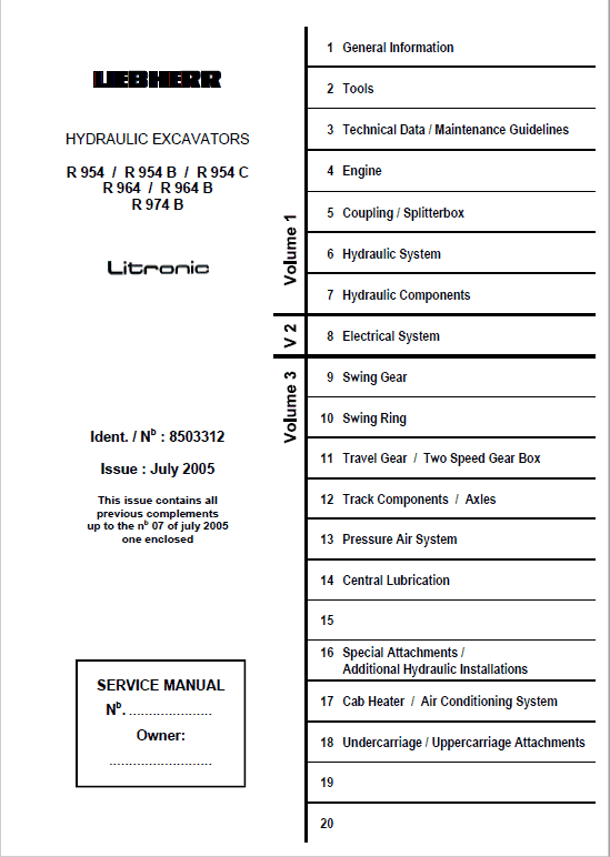
Liebherr R954, R954B, R954C, R964, R964B, R974B Litronic Excavator Service Manual
Liebherr R954, R954B, R954C, R964, R964B, R974B Litronic Excavator Service Manual
Regular price
$36.00 USD
Regular price
Sale price
$36.00 USD
Unit price
/
per
Taxes included.
Shipping calculated at checkout.
Couldn't load pickup availability
R954, R954-HD, R954-V Litronic from serial 101 (Type 406, 494, 629, 630)
R964, R964-HD Litronic from serial 101 (Type 407, 610)
R974, R974B Litronic from serial 1001 (Type 408)
Language: English
Publication: 8503312
Format: PDF
July 2005
Liebherr R954, R954B, R954C, R964, R964B, R974B Litronic Wheel Excavator Service Manual – 1682 Pages
Description
Liebherr R954, R954B, R954C, R964, R964B, R974B Litronic Wheel Excavator Manual
Excavator
Model Applicable from :
R954, R954-HD, R954-V Litronic from serial 101 (Type 406, 494, 629, 630)
R964, R964-HD Litronic from serial 101 (Type 407, 610)
R974, R974B Litronic from serial 1001 (Type 408)
Language: English
Publication: 8503312
Format: PDF
July 2005
Liebherr R954, R954B, R954C, R964, R964B, R974B Litronic Wheel Excavator Service Manual – 1682 Pages
Table of Content of the Service Manual:
1 General information
2 Tools
3 Technical data / Maintenance guidelines
4 Engine
5 Coupling / Splitterbox
6 Hydraulic system
7 Hydraulic components
8 Electrical system
9 Swing gear
10 Swing ring
11 Travel gear / Two Speed Gear Box
12 Track components / Axles
13 Pressure Air System
14 Central Lubrication
16 Special Attachments / Additional Hydraulic Installations
17 Cab Heater / Air Conditioning System
18 Undercarriage / Uppercarriage Attachments
This manual has been prepared to provide you with technical information on the design and construction of the various components which made up the LIEBHERR excavator.
Manual Extract – Working position of spool valve
If a spool valve is moved from its neutral position, the connection from pump to user is open and restricts at the same time the flow to the tank.
The pump pressure rises until it reaches the pressure on the user connection. Oil starts to flow to the user. When the spool valve moves further, the connection from pump to tank closes off and opens the connection for the returning oil from the user to the tank.
The total oil flow from the pump is now available for the user.
The movement of the spool valve depends only on the available control pressure.
This control pressure can be changed continuously depending on the movement of the appropriate joystick (see description and function of the servo control, sub group 7.41).
Due to a negative spool overlap, together with metering notches, the oil flow to the users and thus all working and travel movements, can be controlled by pistons in the control blocks The piston stroke is 15 mm per side on the NS 32, about 30% overlap and about 60% fine control. The remaining stroke is used to regain the nominal diameter.
Springs, which are installed on the upper end of the spool, return the spools to neutral position if control pressure is not available.
Internal leakages on a user connection under pressure are influenced by the overlap and the play between housing and piston. Maximum permissible leak oil, see "Control Valves -Technical Data".
Share


