1
/
of
4
Uploader
Linkbelt 210LX Excavator Service Repair Manual Workshop Guide
Linkbelt 210LX Excavator Service Repair Manual Workshop Guide
Regular price
$42.00 USD
Regular price
Sale price
$42.00 USD
Unit price
/
per
Taxes included.
Shipping calculated at checkout.
Couldn't load pickup availability
Manual Included:
Service Repair Manual:
600 pages
Operators Manual:
244 pages
Hydraulic and Electrical Schematics
Specifications:
Brand:
LinkBelt
Model:
210LX (LX Series)
Applicable for also:
210 LX LF — Long Front
210 LX RB — Road Builder
210 LX TL & 210 LX TL FC — Timber Log-Loader with or without Forestry Cab
210 LX DHP & 210 LX DHP FC— Delimber-Harvester Processor with or without Forestry Cab
Type:
Excavator
Manuals:
Repair and Operators Manual
Publication Numbers:
1032 & 1014
Language:
English
Format:
PDF
Description
Table of Contents
1. General Information
Safety, General Information (1001 7-27690LX)
General Specifications and Special Torque Settings (1002 7-29360-21LX)
2. Engine
Removal and Installation of the Engine (2000 7-28230LX)
Radiator and Oil-Cooler (2001 7-28050LX)
3. Fuel System
Removal and Installation of the Fuel Tank (3001 7-27970LX)
4. Electrical System
Electrical System, Electrical and Electronic Troubleshooting (4001 7-28250-21LX)
Inspection and Maintenance of Batteries and Connecting a Booster Battery (4002 7-27921LX)
Main and Engine Electronic Control Boxes (4003 7-27931-21LX)
5. Undercarriage
Removal and Installation of the Tracks Set (5001 7-27750LX)
Upper and Lower Rollers (5003 7-27770-21LX)
Sprocket (5004 7-27781LX)
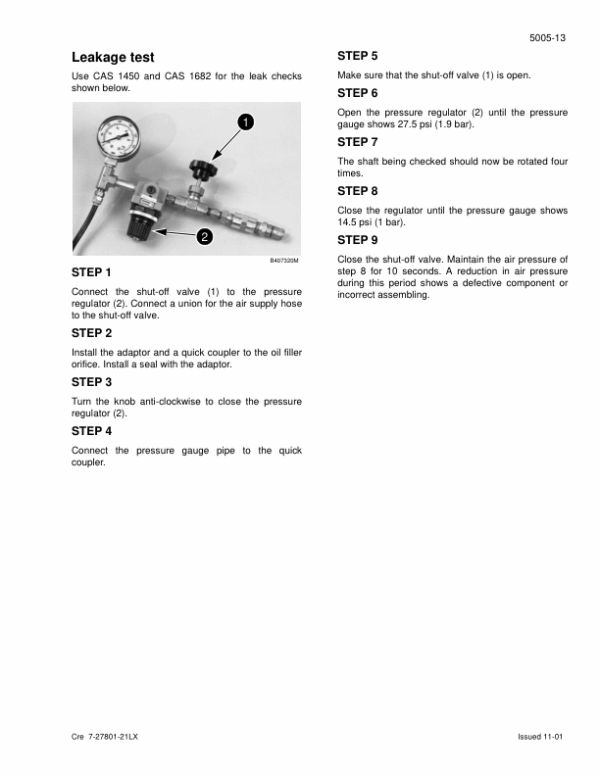
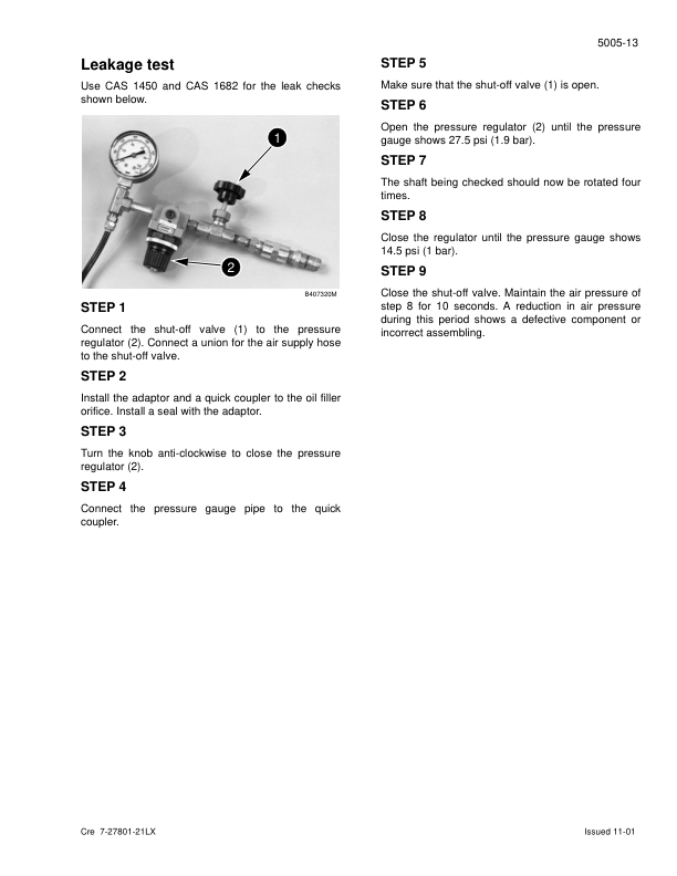
Idler Wheel and Tension Shock Absorber (5005 7-27801-21LX)
6. Drive Train
Drive Motor and Final Drive Transmission Removal and Installation (6001 7-27841LX)
Drive Motor and Final Drive Transmission Disassembly and Assembly (6002 7-28090LX)
Swing Reduction Gear, Removal and Installation (6003 7-27820LX)
Swing Reduction Gear, Disassembly and Assembly (6004 7-28370LX)
7. Undercarriage Hydraulics
Undercarriage Hydraulics Overview
8. Upper Structure Hydraulics
Depressurizing and Decontaminating the Hydraulic System, Use of the Vacuum Pump and Bleeding the Components (8000 7-27951-21LX)
Specifications, Troubleshooting, Checks and Hydraulic Pressure Settings (8001 7-28270-21LX)
Hydraulic Sump Tank Removal and Installation (8002 7-27990LX)
Main and Pilot Pumps, Removal and Installation (8003 7-27860LX)
Main Hydraulic Control Valve, Removal and Installation (8004 7-27890LX)
Attachment Cylinders, Removal and Installation (8005 7-27791LX)
Rotating Joint, Removal and Installation (8006 7-27811LX)
Pilot Blocks, Removal and Installation (8007 9-35590LX)
Swing Motor, Removal and Installation (8008 7-28070LX)
Free Swing, Disassembly and Assembly (8009 9-35530LX)
Main Hydraulic Pump, Disassembly and Assembly (8010 7-35490LX)
Main Hydraulic Control Valve, Disassembly and Assembly (8011 9-36270LX)
Attachment Cylinders, Disassembly and Assembly (8012 7-27900-21LX)
Hand Joystick Control, Disassembly and Assembly (8013 7-28110LX)
Foot Joystick Control, Disassembly and Assembly (8014 7-28210LX)
Six Stack Solenoid Valve, Disassembly and Assembly (8015 7-27910LX)
Cushion Control, Disassembly and Assembly (8016 7-27940LX)
Hose Burst Check Valve (8017 7-29630-21LX)
Rotating Joint, Disassembly and Assembly (8018 7-28080LX)
Swing Motor, Disassembly and Assembly (8019 7-28010LX)
Hydraulic Functions (8020 7-28420-21LX)
9. Upper Structure
Upper Structure, Turntable, and Counterweight (9002 7-27981-21LX)
Boom, Arm, and Bucket (9003 7-27961-21LX)
Seat and Safety Belt (9004 7-28120LX)
Cab and Cab Equipment (9005 7-28021-21LX)
Share