1
/
of
4
Uploader
Linkbelt LS-1600 C2 Excavator Service Repair Manual Workshop Guide
Linkbelt LS-1600 C2 Excavator Service Repair Manual Workshop Guide
Regular price
$38.00 USD
Regular price
Sale price
$38.00 USD
Unit price
/
per
Taxes included.
Shipping calculated at checkout.
Couldn't load pickup availability
Manual Included:
Service Repair Manual:
490 pages
Operators Manual:
120 pages
Hydraulic and Electrical Schematics
Specifications:
Brand:
LinkBelt
Model:
LS 1600 C Series II
Type:
Excavator
Manuals:
Repair and Operators Manual
Publication Numbers:
789 and 790
Language:
English
Format:
PDF
Description
Table of Contents (Service Manual)
1. Caution for Inspection and Maintenance
Basic Rules
General Rules for Disassembling
Pre-Disassembly
Cautions for Disassembling
General Rules for Reassembling
After Disassembly
Cautions for Reassembly
Handling of Interchangeable (Common) Parts
Packings
O-Ring
Oil Seal
Bearing
Snap Ring
Conversion Tables
Length
Area
Volume
Mass
Pressure
Torque
Temperature
Circuit Diagrams
Hydraulic Circuit (For Blade)
Hydraulic Circuit (For Offset)
Electric Circuit
Performance Standards
Measuring Pressure
Accumulator
Hydraulic System Relief Valve Adjustment
Main Relief Pressure
Main Control Valve Port Relief Pressure
Pilot Circuit Pressure
Swing Cross Over Relief Pressure
Points to Note for Replacement of Main Hydraulic Device
Hydraulic Oil Pressure Release
Hydraulic Pump
Swing Motor
Travel Motor
Hydraulic Cylinder
2. Undercarriage
Travel Device
Removal and Installation
Drive Sprocket
Removal and Installation
Take-Up Roller
Removal and Installation
Structural Diagram
Tools and Jigs
Disassembly and Reassembly
Upper Roller
Removal and Installation
Structural Diagram
Tools and Jigs
Disassembly and Reassembly
Lower Roller
Removal and Installation
Structural Diagram
Tools and Jigs
Disassembly and Reassembly
Recoil Spring
Removal and Installation
Structural Diagram
Disassembly and Reassembly
Grease Cylinder
Removal and Installation
Structural Diagram
Tools and Jigs
Disassembly and Reassembly
Track Shoe
Removal and Installation
Structural Diagram
Exchange Procedure
Rotating Joint
Removal and Installation
3. Upper Structure
Swing Device
Removal and Installation
Engine and Radiator Mounting
Engine Installation
Radiator Installation
Hydraulic Pump
Removal and Installation
Holding Valve
Removal and Installation
Control Valve
Removal and Installation
Pilot Valve
Removal and Installation
Manifold Valve
Removal and Installation
Stack Valve
Removal and Installation
4. Attachment
Bucket Cylinder
Removal and Installation
Arm Cylinder
Removal and Installation
Boom Cylinder
Removal and Installation
Off-Set Cylinder
Removal and Installation
Blade Cylinder
Removal and Installation
5. Electrical System
Monitor System
Outline of Monitor System
Configuration of System
Monitor Display Section
Operation Indication
Removal and Installation of Monitor Display Section
Removal
Disassembly and Replacement
Installation
Battery
6. Maintenance
Hydraulic Pump
Maintenance Outline
Disassembly
Maintenance Procedure
Reassembly Procedure
Travel Motor
Maintenance Outline
Disassembly
Maintenance Procedure
Reassembly
Performance Checking Test
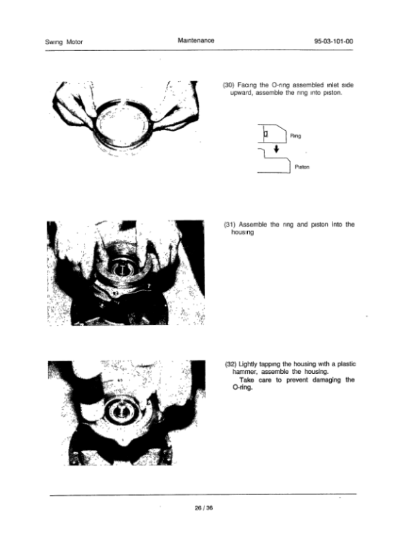
Swing Motor
Maintenance Outline
Cautionary Points for Disassembly and Reassembly
Reassembly Procedure
Maintenance Standards
Control Valve
Maintenance Outline
Disassembly
Cleaning
Inspection
Assembly
Installation
Operation
General Specifications of Control Valve
Troubleshooting
Hydraulic Cylinder
Cylinder Construction
Cautionary
Maintenance
Troubleshooting
Storage Standard
Disassembly and Reassembly
Pilot Valve
Summary
Model Code Numbers
Specifications
Construction
Functions
Actuation
Structural Diagram
Tools and Jigs
Disassembly
Maintenance Standards
Reassembly
Troubleshooting
Rotating Joint
Structural Diagram
Tools and Jigs
Tightening Torques for Bolts
Disassembling Procedure
Reassembling Procedure
Holding Valve
Maintenance Outline
Adjustment of Relief Valve
Disassembling Procedure
Assembling Procedure
Manifold Valve
Maintenance Outline
Adjustment of Relief Valve
Disassembling Procedure
Assembling Procedure
7. Maintenance Standards
Drive Sprocket
Take-Up Roller
Upper Roller
Lower Roller
Track Shoe
Turnable Bearing and Pinion
Attachment Clearance Adjusting Shims
Weight of Components
Tightening Torque Table
Share