1
/
of
4
Uploader
Massey Ferguson 5335, 5340, 5360, 5365 Tractor Service Manual Workshop Guide
Massey Ferguson 5335, 5340, 5360, 5365 Tractor Service Manual Workshop Guide
Regular price
$34.00 USD
Regular price
Sale price
$34.00 USD
Unit price
/
per
Taxes included.
Shipping calculated at checkout.
Couldn't load pickup availability
Massey Ferguson 5335, 5340, 5360, 5365 Tractors Workshop Manual – 697 Pages
Format: PDF
Language: English
Issue 02 – 03 / 2003
Description
Massey Ferguson 5335, 5340, 5360, 5365 Tractor Manual
Model:
Massey Ferguson
MF 5300 Series Tractor
Format: PDF
Language: English
Issue 02 – 03 / 2003
Massey Ferguson 5335, 5340, 5360, 5365 Tractors Workshop Manual – 697 Pages
Content of this Manual – structure in sections
A ……… Introduction
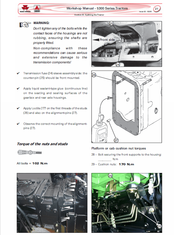
B ………. Splitting the tractor
C ……….2WD front axle
D………. Carraro 4WD front axle: Ca 20.19 and 20.21
E ………. Perkins engines
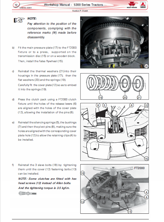
F ……….Clutches
G1…….. Eaton Synchromesh 12×4 gearbox
G2…….. 18×6 speed gearbox – SpeedShift
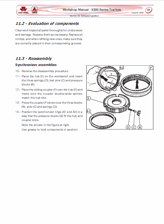
G3…….. 8×8 speed gearbox
G4…….. 12×12 speed gearbox
G5…….. 12×12 speed gearbox with creeper
H ……….Rear axle
I1……… Ferguson hydraulic lift system
I2……… Boschtronic hydraulic lift system
J……….. Power take-off: live and independent
L ………. Electrical system
M ……… Auxiliary hydraulic system
N………. Cab, ar conditioning system and heating
O……….Tractors' general specifications
The purpose of this Workshop Manual is to help Dealers in the efficient maintenance of Massey Ferguson 5300 Series Advanced Tractors.
Compression test for cylinders
Compression is the pressure reached at the end of the piston compression stage.
A compression test can reveal problems of sealing in piston rings, valves, or in the cylinder head gasket or even if the cylinder head is cracked, determining whether or not the engine needs to be split.
The compression test is extremely important to allow comparative analysis among cylinders: increased differences in the readings will indicate irregularities.
Test procedure
a) Check if the valves of all cylinders are adjusted: a strangled valve, for example, may interfere in the reading.
b) Remove the primary element from the air cleaner, and decrease the restriction in the air intake as much as possible.
c) Clean the engine's upper side and remove the nozzles, protecting the housing holes against dust.
d) Install the pressure gauge on the cylinders, as shown in the schematic drawing at side.
e) Actuate the starter motor and record the reading indicated on the pressure gauge (1).
f) Follow the same procedure with the other cylinders.
Share


