1
/
of
4
Uploader
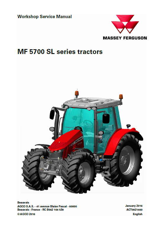
Massey Ferguson 5710 SL, 5711 SL, 5712 SL, 5713 SL Tractor Service Manual Workshop Guide
Massey Ferguson 5710 SL, 5711 SL, 5712 SL, 5713 SL Tractor Service Manual Workshop Guide
Regular price
$37.00 USD
Regular price
Sale price
$37.00 USD
Unit price
/
per
Taxes included.
Shipping calculated at checkout.
Couldn't load pickup availability
Massey Ferguson 5710 SL, 5711 SL, 5712 SL, 5713 SL Tractors Workshop Manual – 1366 Pages
Spicer Axle 730/563 Service Manual – 74 Pages
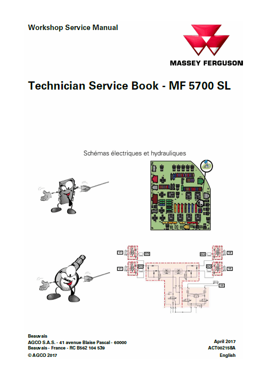
Technician Service Book MF 5700 SL -456 Pages
Parts Catalog (Dyna 4 & Dyna 6) – 532 Pages & 518 Pages
Format: PDF
Language: English
Publication No: ACT0021460
Description
Massey Ferguson 5710 SL, 5711 SL, 5712 SL, 5713 SL Tractor Manual
Model:
Massey Ferguson
MF 5700SL Series Tractor
Format: PDF
Language: English
Publication No: ACT0021460
Massey Ferguson 5710 SL, 5711 SL, 5712 SL, 5713 SL Tractors Workshop Manual – 1366 Pages
Spicer Axle 730/563 Service Manual – 74 Pages
Technician Service Book MF 5700 SL -456 Pages
Parts Catalog (Dyna 4 & Dyna 6) – 532 Pages & 518 Pages
Manual Table of Content
1 Introduction
2 Separation of assemblies
3 Engine
4. Clutch
5. Gearbox
6. Rear axle
7. Power Take Off
8. Front axle
9. Hydraulics
10. Electricity
11. Electronics
12 Cab
13 Accessories
14 Service tools
GPA50/Rear PTO with two electrohydraulic speeds
General
The unit fitted to the rear of the GPA50 rear axle contains all the mechanical components of the two speed rear PTO. These elements rest on tapered roller bearings for which certain cups are fitted "tightened" and others are "free" in the single-piece housing.
The two-speed rear PTO is independent of the transmission.
Changing between the speeds (540 – 540E) of the two-speed PTO is managed hydraulically via the electronic system of the tractor.
In this section, only a partial description is given of each component, as more specific and detailed descriptions are given in their respective sections.
The two-speed rear PTO is divided into four parts: • The clutch The clutch is located on the upper power take-off shaftline and at the front of the center housing. The front part is fitted with a Gerotor type lubrication pump which lubricates the clutch and the gearbox. It is supported by two ball bearings fitted in a support mounted on the center housing.
• The upper shaftline
The upper shaftline of the rear PTO transmits the engine speed to the drive gears of the rear PTO unit via the clutch and a line consisting of three shafts. The drive gears are housed in a single-piece housing.
The tapered roller bearings supporting the drive shaft and gears are shimmed with a preload using shim(s) inserted between the front bearing cup and the single-piece housing cover plate.
• The lower shaftline
The rear PTO lower shaftline is supported by two tapered roller bearings mounted respectively in the single-piece housing
The bearings are held in position by a nut screwed to the front end of the output shaft. Shimming by preloading the tapered roller bearings is achieved using shims which are inserted between the front bearing cup and the single-piece housing.
A lip seal fitted to the single-piece housing ensures the output shaft tightness.
Improved sealing is provided for cases of prolonged use in damp environments such as paddy fields. A special seal is then fitted to the end of the output shaft.
The output shaft is fitted with an interchangeable end (E) which can have 6 or 21 splines.
NOTE: The number of splines on the output shaft depends on the nature of the driven implement and the required rotation speed.
Share


