1
/
of
4
Uploader
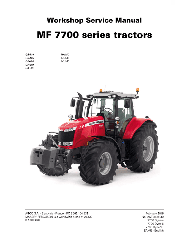
Massey Ferguson 7719, 7720, 7722, 7724, 7726 Tractor Service Manual Workshop Guide
Massey Ferguson 7719, 7720, 7722, 7724, 7726 Tractor Service Manual Workshop Guide
Regular price
$39.00 USD
Regular price
Sale price
$39.00 USD
Unit price
/
per
Taxes included.
Shipping calculated at checkout.
Couldn't load pickup availability
Massey Ferguson 7719, 7720, 7722, 7724, 7726 Tractors Workshop Manual – 3321 Pages
Technician Service Book Series Tractors – 846 Pages
Parts Catalog – 562 Pages & 535 Pages
Format: PDF
Language: English
Publication No: ACT0009130
February 2015
Description
Massey Ferguson 7719, 7720, 7722, 7724, 7726 Tractor Manual
Model:
Massey Ferguson
MF 7700 Series Tractor
Format: PDF
Language: English
Publication No: ACT0009130
February 2015
Massey Ferguson 7719, 7720, 7722, 7724, 7726 Tractors Workshop Manual – 3321 Pages
Technician Service Book Series Tractors – 846 Pages
Parts Catalog – 562 Pages & 535 Pages
Manual Table of Content
1 Introduction
2 Separation of assemblies
3 Engine
4. Clutch
5. Gearbox
6. Rear axle
7. Power Take Off
8. Front axle
9. Hydraulics
10. Electricity
11. Electronics
12 Cab
13 Accessories
14 Service tools
Power Take Off (PTO)
The housing fitted to the rear of the GPA40 rear axle contains all the mechanical components of the rear PTO
function.
The rear PTO can be divided into five sections:
– The clutch
The clutch is located on the upper PTO shaftline and at the front of the centre housing. It is supported by two ball bearings fitted in a support mounted on the centre housing.
– The upper shaftline
The upper shaftline transmits the engine speed to the drive gears located inside the rear housing of the PTO via the clutch and a series of three shafts. The tapered roller bearings supporting the driving gear shaft are shimmed with a clearance using shim(s) inserted between the front bearing cup and the removable compartment.
– The lower shaftline
The lower shaftline is supported by two tapered roller bearings fitted in the rear PTO housing and in the removable compartment.
The tapered roller bearings are held in position by a nut screwed onto the front end of the output shaft.
The preload shimming of the tapered roller bearings is carried out using shim(s) inserted between the front bearing cup and the removable compartment.
The output shaft is sealed by a lip seal fitted into the rear PTO housing.
The output shaft is fitted with an interchangeable end fitting which may be: – of varying length
– fitted with 6, 20 or 21 splines.
– The power take-off brake
The rear PTO is fitted with a brake housed inside the rear housing opposite the 1000-rpm driven gear.
NOTE: The rear PTO brake gradually slows down the output shaft inertia until it stops completely when the rear PTO clutch is disengaged. It is also used to immobilise the gear trains (driving and driven gears).
– Control
The PTO can be controlled mechanically by cables or hydraulically by solenoid valves.
Share


