1
/
of
4
Uploader
Sumitomo SH75X-6A Hydraulic Excavator Repair Service Manual
Sumitomo SH75X-6A Hydraulic Excavator Repair Service Manual
Regular price
$44.00 USD
Regular price
Sale price
$44.00 USD
Unit price
/
per
Taxes included.
Shipping calculated at checkout.
Couldn't load pickup availability
Sumitomo
Excavator SH75X-6A
Format: PDF
Manual Identification: WLSM0756-00T, WDL0756-2T, WCL0756-0T
English
Mar 2014
Sumitomo SH75X-6A Hydraulic Excavator Repair Service Manual – 1252 Pages
Operators Manual – 272 Pages
Parts Catalog – 528 Pages
Description
Sumitomo SH75X-6A Hydraulic Excavator Repair Service Manual
Sumitomo
Excavator SH75X-6A
Format: PDF
Manual Identification: WLSM0756-00T, WDL0756-2T, WCL0756-0T
English
Mar 2014
Sumitomo SH75X-6A Hydraulic Excavator Repair Service Manual – 1252 Pages
Operators Manual – 272 Pages
Parts Catalog – 528 Pages
Sumitomo SH75X-6A Manual TABLE OF CONTENTS
Safety………………………………………………………………………………………………………………… 3
Safety, general information and standard torque data…………………………………………… 4
General Information…………………………………………………………………………………………. 5
Standard Torque Data For Cap Screws And Nuts………………………………………………. 11
Specifications And Special Torque Settings………………………………………………………. 12
Abbreviation………………………………………………………………………………………………….. 13
Specifications………………………………………………………………………………………………… 20
Main Equipment Table……………………………………………………………………………………. 29
Overall View………………………………………………………………………………………………….. 40
WORK RANGE DIAGRAM……………………………………………………………………………… 44
Main Unit Weight…………………………………………………………………………………………… 48
FLUIDS AND LUBRICANTS……………………………………………………………………………. 64
Circuits and Operation explanation…………………………………………………………………… 69
Main Equipment Structure and Operation Explanation………………………………………… 72
Hydraulic Pump…………………………………………………………………………………………….. 73
Travel Motor………………………………………………………………………………………………….. 82
Swing Motor………………………………………………………………………………………………….. 97
3 Stack Solenoid Valve Operation Explanation………………………………………………… 111
Upper Pilot Valve (remote control valve)…………………………………………………………. 113
Travel Pilot Valve (remote control valve)…………………………………………………………. 119
Blade Pilot Valve (remote control valve)………………………………………………………….. 124
Option Pilot Valve (remote control valve)………………………………………………………… 126
Cushion Valve …………………………………………………………………………………………….. 129
Reverse Prevention Valve…………………………………………………………………………….. 133
2 Stack Solenoid Valve…………………………………………………………………………………. 142
Direction Valve (3-direction) (option)………………………………………………………………. 143
Shut-off Valve……………………………………………………………………………………………… 144
HBCV…………………………………………………………………………………………………………. 145
Engine Summary…………………………………………………………………………………………. 147
Hydraulic Equipment Layout………………………………………………………………………….. 192
Overall View………………………………………………………………………………………………… 193
Port Diagram……………………………………………………………………………………………….. 197
Hydraulic Device………………………………………………………………………………………….. 216
Electrical and Engine Functions and Service Support……………………………………….. 217
Basic Functions…………………………………………………………………………………………… 218
Service Support…………………………………………………………………………………………… 261
Maintenance precautions………………………………………………………………………………. 301
Electrical Equipment Layout Diagram……………………………………………………………… 315
Connection Connector Pin Layout………………………………………………………………….. 342
Sequence Circuit Diagram…………………………………………………………………………….. 345
Removal / Installation and Assembly / Disassembly………………………………………… 361
Pressure Bleeding Operations……………………………………………………………………….. 369
Removal and Installation of Track………………………………………………………………….. 370
Removal and Installation of Shoe Assembly……………………………………………………. 371
Removal and Installation of Shoe Plate…………………………………………………………… 374
Removal and Installation of Roller………………………………………………………………….. 375
Removal and Installation of Upper Roller………………………………………………………… 376
Assembly and Disassembly of Upper Roller…………………………………………………….. 378
Removal and Installation of Lower Roller………………………………………………………… 383
Assembly and Disassembly of Lower Roller…………………………………………………….. 385
Removal and Installation of Drive Sprocket……………………………………………………… 390
Removal and Installation of Take-up Roller……………………………………………………… 391
Assembly and Disassembly of Take-up Roller…………………………………………………. 393
Removal and Installation of Grease Cylinder…………………………………………………… 401
Assembly and Disassembly of Tension Shock Absorber…………………………………… 403
Removal and Installation of Center Joint…………………………………………………………. 406
Assembly and Disassembly of Center Joint…………………………………………………….. 408
Removal and Installation of Travel Motor………………………………………………………… 416
Assembly and Disassembly of Travel Motor…………………………………………………….. 418
Removal and Installation of Swing Unit…………………………………………………………… 464
Assembly and Disassembly of Swing Motor…………………………………………………….. 467
Assembly and Disassembly of Swing Unit……………………………………………………….. 485
Removal and Installation of Hydraulic Pump……………………………………………………. 494
Removal and Installation of Pump Coupling…………………………………………………….. 497
Procedures for Assembly and Disassembly of Hydraulic Pump Main Unit……………. 498
Pump Main Unit Maintenance Standards………………………………………………………… 504
Removal and Installation of Control Valve……………………………………………………….. 514
Procedures for Assembly and Disassembly of Control Valve……………………………… 521
Removal and Installation of Engine Assembly………………………………………………….. 551
Removal and Installation of Fuel Cooler, Engine Intercooler, Radiator, and Oil
Cooler………………………………………………………………………………………………………… 556
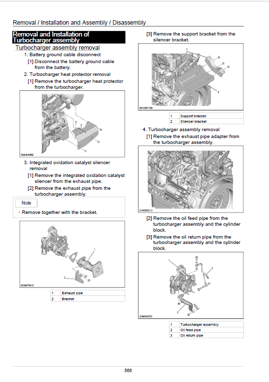
Removal and Installation of Turbocharger assembly…………………………………………. 566
Removal and Installation of EGR Valve…………………………………………………………… 570
Removal and Installation of Engine Hood………………………………………………………… 572
Removal and Installation of Muffler………………………………………………………………… 573
Removal and Installation of Cylinder Head Cover…………………………………………….. 574
Removal and Installation of Idle gear……………………………………………………………… 600
Removal and Installation of Cylinder Block……………………………………………………… 608
Lubrication System………………………………………………………………………………………. 640
Cooling System……………………………………………………………………………………………. 650
Disassembly, Removal and Installation of Crankshaft……………………………………….. 657
Disassembly, Removal and Installation of Piston……………………………………………… 688
Removal and Installation of Camshaft…………………………………………………………….. 711
Removal and Installation of Flywheel……………………………………………………………… 732
Removal and Installation of Crankshaft front oil seal…………………………………………. 735
Removal and Installation of Crankshaft rear oil seal…………………………………………. 739
Removal and Installation of Rocker arm shaft………………………………………………….. 745
Removal and Installation of Valve spring…………………………………………………………. 752
Removal and Installation of Valve stem oil seal……………………………………………….. 769
Removal and Installation of Intake chamber…………………………………………………….. 787
Removal and Installation of Integrated oxidation catalyst silencer………………………. 791
Removal and Installation of Generator……………………………………………………………. 793
Removal and Installation of Exhaust Manifold………………………………………………….. 799
Removal and Installation of Fuel Supply Pump………………………………………………… 805
Removal and Installation of Common Rail Assembly………………………………………… 810
Removal and Installation of Injector………………………………………………………………… 812
Removal and Installation of Starter Motor……………………………………………………….. 817
Removal and Installation of Alternator…………………………………………………………….. 818
Preheating System………………………………………………………………………………………. 820
Introduction to the trouble diagnosis……………………………………………………………….. 825
Removal and Installation of Fuel Tank……………………………………………………………. 849
Removal and Installation of Hydraulic Tank…………………………………………………….. 852
Removal and Installation of Pilot Blocs……………………………………………………………. 857
Removal and Installation of Travel Remote Control Valve…………………………………. 858
Procedures for Assembly and Disassembly of Travel Remote Control Valve……….. 861
Removal and Installation of Option Remote Control Valve…………………………………. 874
Assembly and Disassembly Procedures of Option Remote Control Valve……………. 877
Removal and Installation of Operation Remote Control Valve……………………………. 885
Procedures for Assembly and Disassembly of Operation Remote Control Valve….. 893
Removal and Installation of Blade Remote Control Valve………………………………….. 904
Assembly and Disassembly Procedures…………………………………………………………. 907
Removal and Installation of 3 Stack Solenoid………………………………………………….. 915
Removal and Installation of Cushion Valve……………………………………………………… 917
Assembly and Disassembly of Cushion Valve………………………………………………….. 919
Removal and Installation of Operator's Seat……………………………………………………. 920
Removal/installation of the KAB Seat……………………………………………………………… 921
Removal and Installation of Cab Assembly……………………………………………………… 922
Removal and Installation of Wiper………………………………………………………………….. 926
Removal and Installation of Wiper Controller…………………………………………………… 927
Removal and Installation of Wiper Motor…………………………………………………………. 928
Removal and Installation of ECM…………………………………………………………………… 930
Removal and Installation of Computer A…………………………………………………………. 931
Removal and Installation of Computer B…………………………………………………………. 932
Removal and Installation of Monitor……………………………………………………………….. 933
Removal and Installation of Cab Front Glass…………………………………………………… 935
Window Lock Adjustment Procedures…………………………………………………………….. 937
Tightening torque…………………………………………………………………………………………. 939
Removal and Installation of Counterweight……………………………………………………… 940
Removal and Installation of Bucket………………………………………………………………… 944
Removal and Installation of Bucket Link………………………………………………………….. 946
Removal and Installation of Arm…………………………………………………………………….. 948
Removal and Installation of Boom………………………………………………………………….. 950
Removal and Installation of Blade………………………………………………………………….. 954
Removal and Installation of Bucket Cylinder……………………………………………………. 956
Removal and Installation of Arm Cylinder………………………………………………………… 959
Removal and Installation of Boom Cylinder……………………………………………………… 963
Removal and Installation of Blade Cylinder……………………………………………………… 967
Procedures for Operation/Assembly and Disassembly of Hydraulic Cylinder
(made by KYB)……………………………………………………………………………………………. 971
Removal and Installation of HBCV……………………………………………………………….. 1002
List of special tools…………………………………………………………………………………….. 1004
Maintenance standards and Measurement procedures………………………………….. 1023
Pressure Measurement and Adjustment Procedures………………………………………. 1024
Hydraulic Pump Flow Measurement Procedures……………………………………………. 1037
Drain Volume Measurement Procedures……………………………………………………….. 1041
Air Bleed Procedure……………………………………………………………………………………. 1044
Maintenance Standards………………………………………………………………………………. 1047
Bolt Size and Torque Table…………………………………………………………………………. 1067
New Machine Performance Judgment Table………………………………………………….. 1072
Air Conditioning…………………………………………………………………………………………… 1083
Air Conditioner Overall Diagram…………………………………………………………………… 1084
Assembly and Disassembly of Unit………………………………………………………………. 1124
Removal and Installation of Compressor……………………………………………………….. 1129
Removal and Installation of Condenser…………………………………………………………. 1130
Removal and Installation of Receiver Dryer…………………………………………………… 1132
Work Precautions………………………………………………………………………………………. 1134
Troubleshooting…………………………………………………………………………………………… 1143
Engine-side Diagnostic Trouble Code List……………………………………………………… 1146
Main Unit-side Diagnostic Trouble Code List………………………………………………….. 1148
Diagnostic Trouble Code Display on the Front Screen…………………………………….. 1149
Engine-side Trouble……………………………………………………………………………………. 1150
Main Unit-side Trouble………………………………………………………………………………… 1197
Symptom…………………………………………………………………………………………………… 1229
Data Reference Values……………………………………………………………………………….. 1241
The Sumitomo Manual Preface
The purpose of this Sumitomo Excavator manual is to assist dealers and repair serviceman in efficient repair and maintenance of their machinery. Carrying out the procedures as detailed, together with the use of any special tools needed.
Using the Sumitomo SH75X-6A Manual
To make information easier to find, there is an index at the beginning of each section listing the various parts in that section. At the beginning of each part there is a table of contents which should also be used as a guide to locate information.
To assist with locating information, each section of the manual is preceded by a contents page listing the repair operations, Each instruction within an operating has a sequence number. To complete the operation in the minimum time is possible follow the manual guideline and repair instructions.
When parts have to be replaced in either the SH75X-6A Hydraulic Excavator , it is essential that only genuine Sumitomo parts should be used. Special attention should be paid to the following points concerning repairs and the fitting of replacement parts and accessories.
Indexing
For convenience the manual is divided into section and parts, each page bearing a section and part number. The sections are subdivided into numbered operation. This simplifies cross referencing and enable the subject to be found easily.
Share