1
/
of
4
Uploader
Sumitomo SH80BS-6A Hydraulic Excavator Repair Service Manual
Sumitomo SH80BS-6A Hydraulic Excavator Repair Service Manual
Regular price
$44.00 USD
Regular price
Sale price
$44.00 USD
Unit price
/
per
Taxes included.
Shipping calculated at checkout.
Couldn't load pickup availability
Sumitomo
Excavator SH80BS-6A
Format: PDF
Manual Identification: WLSM0806-00T, WCL0806-0T, WDL0806-1T
English
Sumitomo SH80BS-6A Hydraulic Excavator Repair Service Manual – 1246 Pages
Operators Manual – 272 Pages
Parts Catalog – 510 Pages
Description
Sumitomo SH80BS-6A Hydraulic Excavator Repair Service Manual
Sumitomo
Excavator SH80BS-6A
Format: PDF
Manual Identification: WLSM0806-00T, WCL0806-0T, WDL0806-1T
English
Sumitomo SH80BS-6A Hydraulic Excavator Repair Service Manual – 1246 Pages
Operators Manual – 272 Pages
Parts Catalog – 510 Pages
Sumitomo SH80BS-6A Manual TABLE OF CONTENTS
Safety………………………………………………………………………………………………………………… 3
Safety, general information and standard torque data…………………………………………… 4
General Information…………………………………………………………………………………………. 5
Standard Torque Data For Cap Screws And Nuts………………………………………………. 11
Specifications And Special Torque Settings………………………………………………………. 12
Abbreviation………………………………………………………………………………………………….. 13
Specifications………………………………………………………………………………………………… 20
Main Equipment Table……………………………………………………………………………………. 24
Overall View………………………………………………………………………………………………….. 34
WORK RANGE DIAGRAM……………………………………………………………………………… 36
Main Unit Weight…………………………………………………………………………………………… 40
FLUIDS AND LUBRICANTS……………………………………………………………………………. 53
Circuits and Operation explanation…………………………………………………………………… 57
Main Equipment Structure and Operation Explanation………………………………………… 60
Hydraulic Pump…………………………………………………………………………………………….. 61
Travel Motor………………………………………………………………………………………………….. 70
Swing Motor………………………………………………………………………………………………….. 85
3 Stack Solenoid Valve Operation Explanation………………………………………………….. 99
Upper Pilot Valve (remote control valve)…………………………………………………………. 101
Travel Pilot Valve (remote control valve)…………………………………………………………. 107
Blade Pilot Valve (remote control valve)………………………………………………………….. 112
Option Pilot Valve (remote control valve)………………………………………………………… 114
Cushion Valve …………………………………………………………………………………………….. 117
Swing Pilot Valve (remote control valve)…………………………………………………………. 121
Reverse Prevention Valve…………………………………………………………………………….. 124
2 Stack Solenoid Valve…………………………………………………………………………………. 133
Direction Valve (3-direction) (option)………………………………………………………………. 134
Shut-off Valve……………………………………………………………………………………………… 135
HBCV…………………………………………………………………………………………………………. 136
Engine Summary…………………………………………………………………………………………. 138
Hydraulic Equipment Layout………………………………………………………………………….. 183
Overall View………………………………………………………………………………………………… 184
Port Diagram……………………………………………………………………………………………….. 188
Hydraulic Device………………………………………………………………………………………….. 207
Electrical and Engine Functions and Service Support……………………………………….. 208
Basic Functions…………………………………………………………………………………………… 209
Service Support…………………………………………………………………………………………… 252
Maintenance precautions………………………………………………………………………………. 292
Electrical Equipment Layout Diagram……………………………………………………………… 306
Connection Connector Pin Layout………………………………………………………………….. 333
Sequence Circuit Diagram…………………………………………………………………………….. 336
Removal / Installation and Assembly / Disassembly………………………………………… 351
Pressure Bleeding Operations……………………………………………………………………….. 359
Removal and Installation of Track………………………………………………………………….. 360
Removal and Installation of Shoe Assembly……………………………………………………. 361
Removal and Installation of Shoe Plate…………………………………………………………… 364
Removal and Installation of Roller………………………………………………………………….. 365
Removal and Installation of Upper Roller………………………………………………………… 366
Assembly and Disassembly of Upper Roller…………………………………………………….. 368
Removal and Installation of Lower Roller………………………………………………………… 373
Assembly and Disassembly of Lower Roller…………………………………………………….. 375
Removal and Installation of Drive Sprocket……………………………………………………… 380
Removal and Installation of Take-up Roller……………………………………………………… 381
Assembly and Disassembly of Take-up Roller…………………………………………………. 383
Removal and Installation of Grease Cylinder…………………………………………………… 391
Assembly and Disassembly of Tension Shock Absorber…………………………………… 393
Removal and Installation of Center Joint…………………………………………………………. 396
Assembly and Disassembly of Center Joint…………………………………………………….. 398
Removal and Installation of Travel Motor………………………………………………………… 405
Assembly and Disassembly of Travel Motor…………………………………………………….. 407
Removal and Installation of Swing Unit…………………………………………………………… 453
Assembly and Disassembly of Swing Motor…………………………………………………….. 456
Assembly and Disassembly of Swing Unit……………………………………………………….. 474
Removal and Installation of Hydraulic Pump……………………………………………………. 483
Removal and Installation of Pump Coupling…………………………………………………….. 486
Procedures for Assembly and Disassembly of Hydraulic Pump Main Unit……………. 487
Pump Main Unit Maintenance Standards………………………………………………………… 493
Removal and Installation of Control Valve……………………………………………………….. 503
Procedures for Assembly and Disassembly of Control Valve……………………………… 510
Removal and Installation of Engine Assembly………………………………………………….. 524
Removal and Installation of Fuel Cooler, Engine Intercooler, Radiator, and Oil
Cooler………………………………………………………………………………………………………… 529
Removal and Installation of Turbocharger assembly…………………………………………. 539
Removal and Installation of EGR Valve…………………………………………………………… 543
Removal and Installation of Engine Hood………………………………………………………… 545
Removal and Installation of Muffler………………………………………………………………… 546
Removal and Installation of Cylinder Head Cover…………………………………………….. 547
Removal and Installation of Idle gear……………………………………………………………… 573
Removal and Installation of Cylinder Block……………………………………………………… 581
Lubrication System………………………………………………………………………………………. 613
Cooling System……………………………………………………………………………………………. 623
Disassembly, Removal and Installation of Crankshaft……………………………………….. 630
Disassembly, Removal and Installation of Piston……………………………………………… 661
Removal and Installation of Camshaft…………………………………………………………….. 684
Removal and Installation of Flywheel……………………………………………………………… 705
Removal and Installation of Crankshaft front oil seal…………………………………………. 708
Removal and Installation of Crankshaft rear oil seal…………………………………………. 712
Removal and Installation of Rocker arm shaft………………………………………………….. 718
Removal and Installation of Valve spring…………………………………………………………. 725
Removal and Installation of Valve stem oil seal……………………………………………….. 742
Removal and Installation of Intake chamber…………………………………………………….. 760
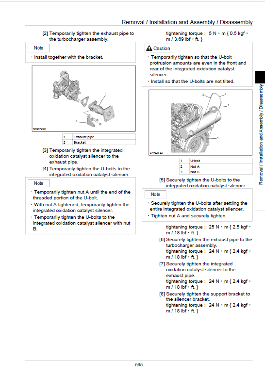
Removal and Installation of Integrated oxidation catalyst silencer………………………. 764
Removal and Installation of Generator……………………………………………………………. 766
Removal and Installation of Exhaust Manifold………………………………………………….. 772
Removal and Installation of Fuel Supply Pump………………………………………………… 778
Removal and Installation of Common Rail Assembly………………………………………… 783
Removal and Installation of Injector………………………………………………………………… 785
Removal and Installation of Starter Motor……………………………………………………….. 790
Removal and Installation of Alternator…………………………………………………………….. 791
Preheating System………………………………………………………………………………………. 793
Introduction to the trouble diagnosis……………………………………………………………….. 798
Removal and Installation of Fuel Tank……………………………………………………………. 822
Removal and Installation of Hydraulic Tank…………………………………………………….. 825
Removal and Installation of Pilot Blocs……………………………………………………………. 830
Removal and Installation of Travel Remote Control Valve…………………………………. 831
Procedures for Assembly and Disassembly of Travel Remote Control Valve……….. 834
Removal and Installation of Option Remote Control Valve…………………………………. 847
Assembly and Disassembly Procedures of Option Remote Control Valve……………. 850
Removal and Installation of Operation Remote Control Valve……………………………. 858
Procedures for Assembly and Disassembly of Operation Remote Control Valve….. 866
Removal and Installation of Blade Remote Control Valve………………………………….. 877
Assembly and Disassembly Procedures…………………………………………………………. 880
Removal and Installation of Swing Remote Control Valve…………………………………. 888
Procedures for Assembly and Disassembly of Swing Remote Control Valve……….. 890
Removal and Installation of 3 Stack Solenoid………………………………………………….. 898
Removal and Installation of Cushion Valve……………………………………………………… 900
Assembly and Disassembly of Cushion Valve………………………………………………….. 902
Removal and Installation of Operator's Seat……………………………………………………. 903
Removal/installation of the KAB Seat……………………………………………………………… 904
Removal and Installation of Cab Assembly……………………………………………………… 905
Removal and Installation of Wiper………………………………………………………………….. 909
Removal and Installation of Wiper Controller…………………………………………………… 910
Removal and Installation of Wiper Motor…………………………………………………………. 911
Removal and Installation of ECM…………………………………………………………………… 913
Removal and Installation of Computer A…………………………………………………………. 914
Removal and Installation of Computer B…………………………………………………………. 915
Removal and Installation of Monitor……………………………………………………………….. 916
Removal and Installation of Cab Front Glass…………………………………………………… 918
Window Lock Adjustment Procedures…………………………………………………………….. 920
Tightening torque…………………………………………………………………………………………. 922
Removal and Installation of Counterweight……………………………………………………… 923
Removal and Installation of Bucket………………………………………………………………… 927
Removal and Installation of Bucket Link………………………………………………………….. 929
Removal and Installation of Arm…………………………………………………………………….. 931
Removal and Installation of Boom………………………………………………………………….. 933
Removal and Installation of Blade………………………………………………………………….. 937
Removal and Installation of Bucket Cylinder……………………………………………………. 939
Removal and Installation of Arm Cylinder………………………………………………………… 942
Removal and Installation of Boom Cylinder……………………………………………………… 946
Removal and Installation of Boom Swing Cylinder……………………………………………. 950
Removal and Installation of Blade Cylinder……………………………………………………… 954
Procedures for Operation/Assembly and Disassembly of Hydraulic Cylinder
(made by KYB)……………………………………………………………………………………………. 958
Removal and Installation of HBCV…………………………………………………………………. 991
List of special tools………………………………………………………………………………………. 993
Maintenance standards and Measurement procedures………………………………….. 1013
Pressure Measurement and Adjustment Procedures………………………………………. 1014
Hydraulic Pump Flow Measurement Procedures……………………………………………. 1027
Drain Volume Measurement Procedures……………………………………………………….. 1031
Air Bleed Procedure……………………………………………………………………………………. 1034
Maintenance Standards………………………………………………………………………………. 1037
Bolt Size and Torque Table…………………………………………………………………………. 1056
New Machine Performance Judgment Table………………………………………………….. 1061
Air Conditioning…………………………………………………………………………………………… 1071
Air Conditioner Overall Diagram…………………………………………………………………… 1072
Assembly and Disassembly of Unit………………………………………………………………. 1112
Removal and Installation of Compressor……………………………………………………….. 1117
Removal and Installation of Condenser…………………………………………………………. 1118
Removal and Installation of Receiver Dryer…………………………………………………… 1120
Work Precautions………………………………………………………………………………………. 1122
Troubleshooting…………………………………………………………………………………………… 1131
Engine-side Diagnostic Trouble Code List……………………………………………………… 1134
Main Unit-side Diagnostic Trouble Code List………………………………………………….. 1136
Diagnostic Trouble Code Display on the Front Screen…………………………………….. 1137
Engine-side Trouble……………………………………………………………………………………. 1138
Main Unit-side Trouble………………………………………………………………………………… 1185
Symptom…………………………………………………………………………………………………… 1224
Data Reference Values……………………………………………………………………………….. 1236
The Sumitomo Manual Preface
The purpose of this Sumitomo Excavator manual is to assist dealers and repair serviceman in efficient repair and maintenance of their machinery. Carrying out the procedures as detailed, together with the use of any special tools needed.
Using the Sumitomo SH80BS-6A Manual
To make information easier to find, there is an index at the beginning of each section listing the various parts in that section. At the beginning of each part there is a table of contents which should also be used as a guide to locate information.
To assist with locating information, each section of the manual is preceded by a contents page listing the repair operations, Each instruction within an operating has a sequence number. To complete the operation in the minimum time is possible follow the manual guideline and repair instructions.
When parts have to be replaced in either the SH80BS-6A Hydraulic Excavator , it is essential that only genuine Sumitomo parts should be used. Special attention should be paid to the following points concerning repairs and the fitting of replacement parts and accessories.
Indexing
For convenience the manual is divided into section and parts, each page bearing a section and part number. The sections are subdivided into numbered operation. This simplifies cross referencing and enable the subject to be found easily.
Share