1
/
of
4
Uploader
Takeuchi TB070 and TB070W Excavator Service Manual Workshop Guide
Takeuchi TB070 and TB070W Excavator Service Manual Workshop Guide
Regular price
$36.50 USD
Regular price
Sale price
$36.50 USD
Unit price
/
per
Taxes included.
Shipping calculated at checkout.
Couldn't load pickup availability
Takeuchi TB070 and TB070W Service Repair Manual – 456 Pages
Takeuchi TB070 Operating Manual – 125 Pages
Parts Manual for TB070 and TB070W – 345 Pages
Engine Manual for TB070 and TB070W – 111 Pages
Description
Takeuchi TB070 and TB070W Excavator Service Manual
Type:
Excavator
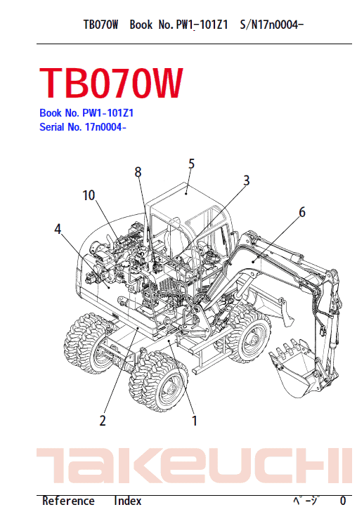
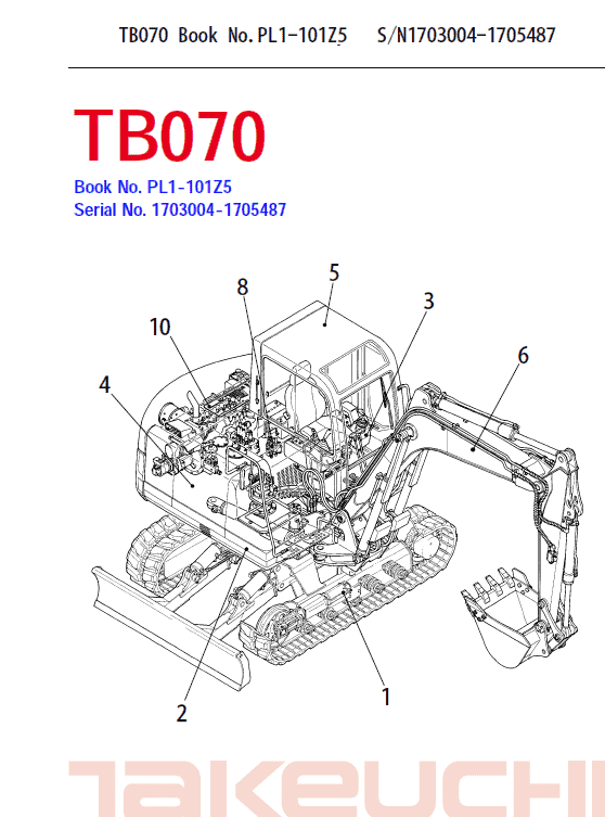
TB070 and TB070W
Format: PDF
Language of the Manual: English
Publication: WL1-101E4
Takeuchi TB070 and TB070W Service Manual – 456 Pages
Takeuchi TB070 Operating Manual – 125 Pages
Parts Manual for TB070 and TB070W – 345 Pages
Engine Manual for TB070 and TB070W – 111 Pages
The manual describes operation, service, repair and maintenance of the excavator, as well as safety instructions that should be follow.
The Takeuchi TB070 and TB070W manual is intended for persons who engage in maintenance operations, and explains procedures for disassembly and reassembly of the machine, check and maintenance procedures, maintenance reference values, troubleshooting and outline specifications, etc. Please use this Takeuchi manual for excavator TB070 and TB070W as a reference in service activities to improve maintenance techniques.
Please note that the contents and diagrams included in this manual may not match your machine exactly.
Items or diagram which manual contains are subject to change without notice due to design modifications, etc. Always store the Takeuchi excavator manual near at hand preferably on the machine itself. When transferring ownership of this machine, be sure to provide the owner manual to the next owner.
Table of Content of TB070 and TB070W Instructions Manual:
I . GENERAL
II . SPECIFICATIONS
III. MACHINE CONFIGURATION
IV. HYDRAULIC UNITS
V . TROUBLESHOOTING
VI. ENGINE
Before operating, perform the prescribe inspections and make repairs immediately should any irregularities be found. If a failure that causes loss of control such as steering, service brakes or engine occurs, stop the machine motion as quickly as possible, follow the shutdown procedure, and keep machine securely park until the problem is fixed.
Extract from the Service Manual:
Disassembling the Main Relief Valve 1. Disassemble plug assembly (1) and sleeve (2), spring (3) and main poppet (4).
• The pilot seat is caulked by the tip of the plug and cannot be disassembled.
2. Remove the lock nut (5), washer (6) and set screw (7) from the plug assembly.
• When assembling, after installing the set screw, first partially tighten the lock nut, then fully tighten it after adjusting the pressure.
3. Remove spring (8) and needle valve (9) from plug assembly (1).
4. Remove O-ring (10), backup ring (11) and O-ring (12) from plug assembly (1).
Disassembling the Anti-cavitation Valve 1. Disassemble plug (1) and wave washer (2), poppet (3) and housing (4).
• Plug Tightening Torque: 7 – 8 kgfm 2. Remove O-ring (5), backup ring (6) and O-ring (7) from plug (I).
3. Remove O-ring (8) from housing (4)
4. Remove spring (9), piston (10) and poppet (11) from poppet (3).
5. Remove O-ring (12) and backup ring (13) from poppet (11);
•
Share