1
/
of
4
Uploader
Toro Reelmaster 5410, 5510, 5610 Service Repair Manual Workshop Guide
Toro Reelmaster 5410, 5510, 5610 Service Repair Manual Workshop Guide
Regular price
$35.00 USD
Regular price
Sale price
$35.00 USD
Unit price
/
per
Taxes included.
Shipping calculated at checkout.
Couldn't load pickup availability
Type: Reelmaster
Language: English
Format: PDF Download
Toro Reelmaster 5410, 5510, 5610 Service Repair Manual – 674 Pages
Description
Toro Reelmaster 5410, 5510, 5610 Service Repair Manual
Type: Reelmaster
Language: English
Format: PDF Download
Toro Reelmaster 5410, 5510, 5610 Service Repair Manual – 674 Pages
Table of Content of the Reelmaster 5410, 5510, 5610
Preface …………………………………………………………………………………………………. 5
Chapter 1: Safety ……………………………………………………………………………….. 1–1
Safety Instructions …………………………………………………………………………… 1–2
Jacking Instructions …………………………………………………………………………. 1–6
Safety and Instructional Decals ………………………………………………………….. 1–7
Chapter 2: Specifications and Maintenance ……………………………………………. 2–1
Specifications ………………………………………………………………………………….. 2–2
Torque Specifications ……………………………………………………………………….. 2–5
Shop Supplies ……………………………………………………………………………….. 2–10
Special Tools …………………………………………………………………………………. 2–12
Chapter 3: Kubota Diesel Engine ………………………………………………………….. 3–1
Specifications ………………………………………………………………………………….. 3–2
General Information …………………………………………………………………………. 3–5
Adjustments…………………………………………………………………………………….. 3–6
Service and Repairs …………………………………………………………………………. 3–8
Chapter 4: Yanmar Diesel Engine………………………………………………………….. 4–1
Specifications ………………………………………………………………………………….. 4–2
General Information …………………………………………………………………………. 4–6
Service and Repairs ……………………………………………………………………….. 4–12
Chapter 5: Kubota Gasoline Engine ………………………………………………………. 5–1
Specifications ………………………………………………………………………………….. 5–2
General Information …………………………………………………………………………. 5–4
Service and Repairs …………………………………………………………………………. 5–6
Chapter 6: Hydraulic System………………………………………………………………… 6–1
Specifications ………………………………………………………………………………….. 6–4
General Information …………………………………………………………………………. 6–6
Hydraulic Schematics ……………………………………………………………………… 6–17
Hydraulic Flow Diagrams (5410/5410-D/5510/5510-D/5610)…………………. 6–20
Hydraulic Flow Diagrams (5610-D) ……………………………………………………. 6–32
Special Tools………………………………………………………………………………….. 6–44
Troubleshooting ……………………………………………………………………………… 6–50
Testing the Hydraulic System……………………………………………………………. 6–56
Service and Repairs ……………………………………………………………………… 6–145
Chapter 7: Electrical System ………………………………………………………………… 7–1
General Information …………………………………………………………………………. 7–3
Special Tools……………………………………………………………………………………. 7–7
InfoCenter Display ……………………………………………………………………………. 7–9
Troubleshooting ……………………………………………………………………………… 7–26
Electrical System Quick Checks………………………………………………………… 7–44
Adjustments…………………………………………………………………………………… 7–46
Testing the Electrical Components …………………………………………………….. 7–54
Service and Repairs ……………………………………………………………………… 7–120
Chapter 8: Chassis……………………………………………………………………………… 8–1
Specifications ………………………………………………………………………………….. 8–2
General Information …………………………………………………………………………. 8–3
Special Tools……………………………………………………………………………………. 8–4
Service and Repairs …………………………………………………………………………. 8–5
Chapter 9: Cutting Unit ………………………………………………………………………… 9–1
Specifications ………………………………………………………………………………….. 9–2
General Information …………………………………………………………………………. 9–4
Special Tools……………………………………………………………………………………. 9–5
Aftercut Appearance ……………………………………………………………………….. 9–10
Adjustments…………………………………………………………………………………… 9–13
Service and Repairs ……………………………………………………………………….. 9–17
Chapter 10: Belt Driven Groomer (Optional)………………………………………….. 10–1
General Information ……………………………………………………………………….. 10–2
Adjustments ………………………………………………………………………………….. 10–4
Service and Repairs ……………………………………………………………………….. 10–6
Chapter 11: Universal Groomer (Optional) ……………………………………………. 11–1
General Information ……………………………………………………………………….. 11–2
Troubleshooting ……………………………………………………………………………… 11–3
Service and Repairs ……………………………………………………………………….. 11–4
Appendix A …………………………………………………………………………………………A–1
Electrical Drawing Designations…………………………………………………………..A–2
Hydraulic Schematic-5410/5410-D ………………………………………………………A–3
Hydraulic Schematic-5510/5510-D/5610 ………………………………………………A–4
Hydraulic Schematic-5610-D ………………………………………………………………A–5
Electrical Schematic-5410/5510/5610 (Models with Kubota Diesel Engine)
(Serial Numbers Below 403430000) …………………………………………………….A–6
Electrical Schematic-5410/5510/5610 (Models with Kubota Diesel Engine)
(Serial Numbers Above 403430000) …………………………………………………….A–7
Electrical Schematic-5410-D/5510-D/5610-D (Models with Yanmar Diesel
Engine) (Serial Numbers Below 403430000) …………………………………………A–8
Electrical Schematic-5410-D/5510-D/5610-D (Models with Yanmar Diesel
Engine) (Serial Numbers Above 403430000)…………………………………………A–9
……………………………………………………………………………………………………..A–10
Electrical Schematic-5410-G/5510-G (Models with Kubota Gasoline
Engine) ………………………………………………………………………………………….A–11
Wire Harness Drawing-Main (Serial Number Below 403430000) …………….A–12
Wire Harness Drawing-Main (Serial Number Below 403430000) …………….A–13
Wire Harness Drawing-Main (Serial Numbers 403430001 to
405680000) ……………………………………………………………………………………A–14
Wire Harness Drawing-Main (Serial Numbers 403430001 to
405680000) ……………………………………………………………………………………A–15
Wire Harness Drawing-Main (Serial Numbers Above 405680001) …………..A–16
Wire Harness Drawing-Main (Serial Numbers Above 405680001) …………..A–17
Wire Harness Drawing-Seat………………………………………………………………A–18
Wire Harness Drawing-Seat………………………………………………………………A–19
Engine Wire Harness Drawing-5410/5510/5610 (Models with Kubota
Diesel Engine) ………………………………………………………………………………..A–20
Engine Wire Harness Diagram-5410/5510/5610 (Models with Kubota
Diesel Engine) ………………………………………………………………………………..A–21
Engine Wire Harness Drawing-5410-D/5510-D (Models 03672 and 03687
with Yanmar Diesel Engine) ………………………………………………………………A–22
Engine Wire Harness Diagram-5410-D/5510-D (Models 03672 and 03687
with Yanmar Diesel Engine) ………………………………………………………………A–23
Engine Wire Harness Drawing-5410-D/5510-D/5610-D (Models 03606,
03607, and 03679)…………………………………………………………………………..A–24
Engine Wire Harness Diagram-5410-D/5510-D/5610-D (Models 03606,
03607, and 03679)…………………………………………………………………………..A–25
Engine Wire Harness Drawing-5410-G/5510-G (Models with Kubota
Gasoline Engine) …………………………………………………………………………….A–26
Engine Wire Harness Diagram-5410-G/5510-G (Models with Kubota
Gasoline Engine) …………………………………………………………………………….A–27
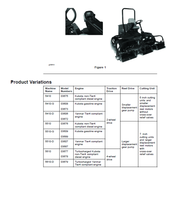
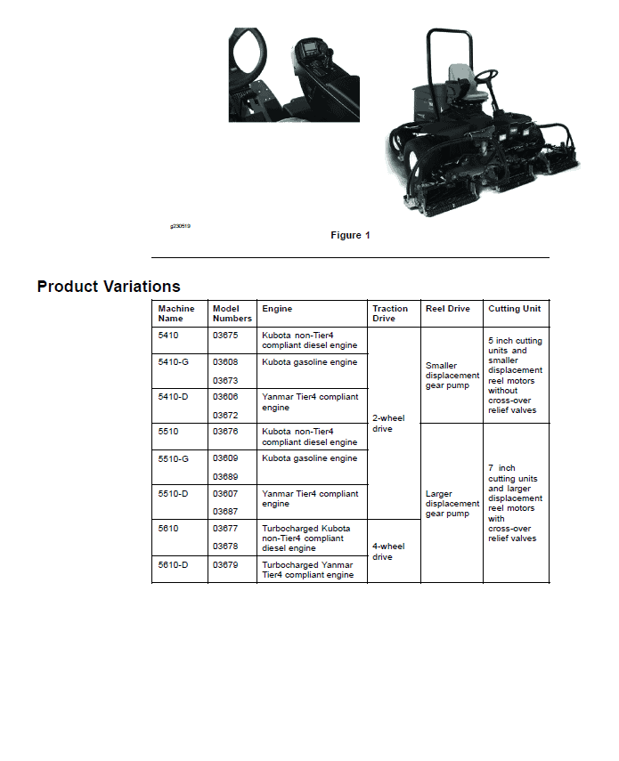
The purpose of this publication is to provide the service technician with information for troubleshooting, testing and repair of major systems and components on the Reelmaster 5410, 5410-G, 5410-D, 5510, 5510-G, 5510-D, 5610, and 5610-D. Equipment model numbers covered in this manual include 03606, 03607, 03608, 03609, 03672, 03673, 03675, 03676, 03677, 03678, 03679, 03687, and 03689. All of these models include an InfoCenter Display on the operator control arm and several of the models comply with EPA Tier 4 emission regulations.
Share