1
/
of
4
Uploader
Volvo A25C 4×4 Articulated Dump Truck Repair Service Manual Workshop Guide
Volvo A25C 4×4 Articulated Dump Truck Repair Service Manual Workshop Guide
Regular price
$48.00 USD
Regular price
Sale price
$48.00 USD
Unit price
/
per
Taxes included.
Shipping calculated at checkout.
Couldn't load pickup availability
Manual Included:
Repair Service Manual:
301 Pages
Specifications:
Brand:
Volvo
Model:
A20 6×4 BM
Type:
Articulated Dump Truck
Manuals:
Repair Service Manual
Publication Numbers:
Ref. No 252954 3588
Language:
English
Format:
PDF
Description
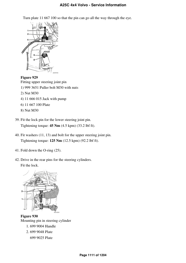
Table of Content A25C 4×4 Service Information
GENERAL
DESCRIPTION, COMPLETE MACHINE
General
SPECIFICATIONS
Specifications, tightening torques
Specifications, dimensions
Volvo standard tightening torques
STANDARD TIME
TOOL
Drawings of E-tools that can be made in your own workshop
STANDARD PARTS, SERVICE
LUBRICANT; FUEL; OTHER FLUID
Brake system, changing brake fluid
SERVICE
Maintenance
Electric welding
Emergency measures
ENGINE WITH MOUNTING AND EQUIPMENT
ENGINE
General, common info about 211 – 218
Compression check, engine at operating temperature
Specifications, general
Cylinder head
Specifications, tightening torques
Cylinder block with crankcase ventilation
Valve mechanism
Valves, adjusting
Engine transmission; camshaft
Crank shaft; connecting rod; vibration damper; fly wheel
Oil sump, dipstick incl.
Engine mounting
LUBRICATING SYSTEM
General, common info about 221 – 224
Oil pump; line
Lubrication oil pressure, checking
FUEL SYSTEM
General (common info about 233 – 238)
Low emission engines
Fuel pump; filter; strainer
Fuel feed pump, checking feed pressure
Fuel tank; fuel filling pump
Specifications, capacities
Injection pump; regulator; pump companion
Fuel injection pump, changing incl. setting injection timing
Idle speed, checking and adjusting
Injection timing TDC, checking and adjusting
Low and high idle speed, checking and adjusting with service display unit
Stall speed, checking with service display unit
Injector; delivery pipe
Injectors, changing all
Control system; control unit (for ex. injection timming adjuster)
Automatic timing adjuster, checking
Automatic timing adjuster (alpha adjuster)
INLET SYSTEM; EXHAUST SYSTEM
Inlet manifold; exhaust manifold
Turbo charger
Air cleaner with connections; air pre-heater
COOLING SYSTEM
General, common info about 261 – 269
Radiator, mounting and connections included
Coolant, changing
Fan; fan shroud; fan coupling
Hydraulic motor for fan, alternatively hydraulic pump, checking internal leakage
Radiator fan drive, checking function of motor
Radiator fan drive, general description
ENGINE CONTROL
Revs control, foot operated
Throttle pedal, anti-throttle cylinder, adjusting
ELEC. SYSTEM; WARNING SYSTEM; INFORMATION SYSTEM; INSTRUMENTS
Comprehensive info, electrical system
Special instructions for servicing the electrical system
BATTERY; ENERGY STORAGE SYSTEM; MOUNTING PARTS
Battery
ALTERNATOR; CHARGING; ELECTRIC MOTOR; ELECTRIC DRIVES
Alternator inclusive drive
Charging, checking in machine (multimeter)
Charging; converter
STARTING SYSTEM
Starter motor inclusive solenoid
LIGHTING
General, common info about 351 – 356
Lighting, front, including parking light and day running light
Headlight, complete, changing 1 headlight incl. adjusting alignment
Headlights, adjusting against wall or fender
CABLE; FUSE; RELAY
General, common info about 371 – 379
A25C 4×4 turn-around wheels (serial no. Ţ€"12483)
Explanations of wiring diagrams
Instrument panel, (serial no. ހ"11100, BR ހ"70300, US 66 ހ"61400, 44 ހ"68200)
Instrument panel, (serial no. 11101Ţ€", BRł 70301Ţ€", US 66 61401Ţ€", 44 68201Ţ€")
Wiring diagrams (serial no. ހ"11100, BR ހ"70300, US 66 ހ"61400, 44 ހ"68200) Circuit 0ހ"6
Wiring diagrams(serial no. 11101Ţ€", BR 70301Ţ€", US 66 61401Ţ€", 44 68201Ţ€") Circuit 0Ţ€"6
Cable; battery disconnector
Code legend for connectors (serial no. 11101Ţ€", BR 70301Ţ€", US 6×6 61401Ţ€", 4×4 68201Ţ€")
Code legend for connectors (serial no. Ţ€"11100, BR Ţ€"70300, US 6×6 Ţ€"61400, 4×4 Ţ€"68200)
Template for pin numbers connector X1/A1
Electrical distribution box; fuse box; junction box
Circuit board, right electrical distribution box(serial no. ހ"11100, BR ހ"70300, US 66 ހ"61400, 44 ހ"68200)
(serial no. 11101ހ", BR 70301ހ", US 66 61401 ހ", 44 68201ހ")
Fuses, left electrical distribution box
Fuses, right electrical distribution box
Other fuses(serial no. ހ"11100, BR ހ"70300, US 66 ހ"61400,
(serial no. 11101ހ", BR 70301ހ", US 66 61401 ހ",
Relays, left electrical distribution box
Relays, right electrical distribution box
INSTRUMENT; SENSOR; WARNING AND INFORMATION SYSTEM
General, common info about 383 – 387
Speedometer; trip meter; hour counter
Speedometer, changing (serial no. 10742Ţ€"11965, BR 70173Ţ€"70388, US 66 61103Ţ€"61623, 44 68157Ţ€"68218)
Speedometer, electric, calibrating
Speedometer, electronic programming instructions
Speedometer, electronic, description (serial no. 11966Ţ€", BR 70389Ţ€", US 6×6 61624 Ţ€", 4×4 68211Ţ€")
Sender, monitoring system
Load sensor, checking electric circuits
Load sensor, adjusting
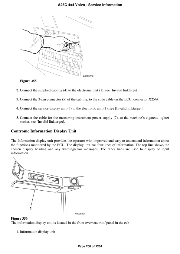
Warning/information unit, display unit
Contronic Information Display Unit
Contronic service display unit
Information display unit, summary
Information on the service display unit
Measuring instrument, summary
Service display unit, summary
Using the service display unit
POWER TRANSMISSION
General, common info about 410 – 436
CLUTCH; TORQUE CONVERTER
Hydrodynamic coupling, torque converter
TRANSMISSION, HYDRAULIC CONTROL
Hydraulic diagram, transmission with retarder from and incl. serial number 93284Ţ€"
up to and incl. serial number ހ"93283
Transmission functions, checking instructions for connector X1/A1
Transmission PT1051 ހ" cut-away drawing
Transmission PT1051, general description
Transmission, general troubleshooting
Troubleshooting outside the control unit in connector X1/A1
Wiring diagram, transmission electronics, circuit 37a-I
Transmission, hydraulic control
Diagnosis using error codes on service display unit
Gearshift selector, checking
Hydraulic transmission, checking oil pressure
Inductive sensor for output shaft, changing
Inductive sensor for turbine speed, changing
Oil cooler, changing
Seal for rear output shaft, changing
Solenoids, checking resistance
Transmission, removing and mounting (engine removed from machine)
Transmission, removing and mounting (together with engine)
GEARBOX,
Distributing gearbox
Dropbox FL 652 C, general description
Dropbox, adjusting high and low range
Dropbox, changing compressed air cylinder for high and low range
Dropbox, changing seal for rear output shaft
Dropbox, changing seal for front output shaft
Longitudinal differential lock, adjusting engagement
PROPELLER SHAFT
General, common info about 451 – 453
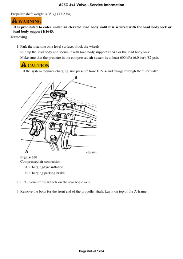
Propeller shaft, complete
Intermediate propeller shaft and/or bearing, changing (in frame joint)
Propeller shaft between transmission and dropbox, changing
Propeller shaft for rear bogie axle, changing
Propeller shaft, front output shaft on dropbox, changing
Propeller shaft for front bogie axle, changing
FRONT AXLE; REAR AXLE
General, common info about 461 – 468
Dog clutch 66, checking and adjusting
Final drive 66 output shaft, changing seals and bearings
Front axle
Front axle complete, removing
Differential lock, with control
Transverse differential lock, adjusting engagement (per axle)
POWER TAKE OFF
Power take off
Power take off, between engine and gearbox (ART)
Flywheel housing (rear engine transmission) and power take-off
Power take-off in flywheel housing, reconditioning
Power take-off in flywheel housing, changing
BRAKE
Comprehensive info about brakes
WHEEL BRAKE
General, common info about 511 – 519
Brake pads for service brake, checking
Specifications, weights
Front wheel brake, dry brake
Brake caliper, changing (per caliper)
Brake disc, changing
HYDRAULIC BRAKE SYSTEM
General, common info about 520 – 522
Brake system, bleeding
Brake valve
PARKING BRAKE
General, common info about 551 – 554
Parking brake caliper removed, reconditioning
Parking brake valve ހ" hand-operated lever
Parking brake valve, reconditioning
Parking brake, changing brake caliper
Parking brake, changing brake disc
Parking brake, changing brake pads
Spring brake cylinder removed, reconditioning
Propeller shaft brake
COMPRESSED-AIR BRAKE
General, common info about 561 – 565
Blocking valve, reconditioning (removed)
Four-way pressure retaining valve, reconditioning (removed)
Compressor; regulator; anti-freez unit
Cut-out and cut-in pressures, checking and adjusting
Cut-out and cut-in pressures, checking and adjusting
Compressed-air tank, with mounting
Valves, compressed-air
MISCELLANEOUS
General, common info about 591 – 594
Compressed air diagram A25C, 4×4 turn-around wheels (serial no. 11101Ţ€", BR 70301Ţ€", US 66 61401 Ţ€", 44 68201Ţ€")
Compressed air diagram A25CTS 6×6 (serial no. Ţ€"12191)
(serial no. 12192Ţ€")
Compressed air diagram A25C, 4×4 turn-around wheels (serial no. Ţ€"11100, BR Ţ€"70300, US 66 Ţ€"61400, US 44 Ţ€"68200)
Compressed air diagram A25C US 44 68201Ţ€")
Compressed air diagram A25C(serial no. ހ"11100, BR ހ"70300, US 66 ހ"61400, US 44 ހ"68200)
Retarder
Functional description, hydraulic retarder
STEERING
Comprehensive info, steering
General, common info about 641 – 647
Pressure accumulation, engine dependent pumps 1 and 2
Steering gear
Steering gear, checking and adjusting
Steering gear, changing
Steering arm; steering linkage; track rod
Steering linkage, changing roller bearings in rear lever
Steering linkage, changing roller bearing in front lever
Steering linkage, checking and adjusting
Hydraulic equipment
Damping cylinder, removing and mounting
Damping cylinder, changing seals
Damping cylinder, checking pre-load
Steering cylinder bearing, checking
Steering cylinder, changing spherical bearing
Steering cylinder, reconditioning in machine (left steering cylinder)
Steering valve removed, reconditioning
Steering valve, changing
Steering cylinder, changing
Steering system, checking and adjusting operating pressure
Steering valve neutral position and valve slide axial clearance, checking
Steering damper
FRAME; SPRINGS; DAMPING; AXLE SUSPENSION; WHEEL/TRACK UNIT
FRAME
Frame, complete
Load unit frame, checking dimensions
SUSPENSION
General, common info about 725 – 727
Hollow rubber spring, bump stop
Front rubber springs, changing all
FRAME LINK
Bearings
Frame joint, checking and adjusting clearance
Frame joint, changing metallic bearing
Steering joint and frame joint
Frame link grader
Frame joint, changing hitch
Steering joint, changing spherical bearings
AXLE SUSPENSION
Movable member system, front/rear
A-frame rubber bushing brackets, adjusting front bracket
Front or rear bogie axle torsion bar, adjusting
Front axle, changing rubber spring (bushing)
Load unit A-frame, changing rubber spring (bushing)
Bogie suspension
Bogie beam, changing rubber springs
Torsion bar and/or rubber bushing, changing on load unit
Torsion bar, checking and adjusting
WHEELS; TRACKS; TYRE; HUB; DRUM
Wheel
MACHINERY HOUSE; CAB; EXTERIOR TRIM PARTS ANYWHERE
CAB, NAKED; CANOPY
TRIM PART, OUTSIDE; GLASS; SEALING MOULDING
Glass; sealing moulding
Window pane, changing
CAB INTERIOR/UPHOLSTERY
Driver's seat, complete; instructor's seat
Air spring for operatorŢ€™s seat, changing
OperatorŢ€™s seat, adjusting height of attachment
OperatorŢ€™s seat, mechanical suspension
AIR CONDITIONING UNIT
Air distribution incl. air intake with filter
Heating unit
Heater, changing
Cooling unit
Filling refrigerant R134a
HYDRAULIC SYSTEM; DIGGING/ HANDLING/ GRADING EQUIPM.; MISC. EQUIP.
WORKING HYDRAULICS; SERVO HYDRAULICS
General, common info about 911 – 917
Hydraulic system and component positions
Hydraulic system, bleeding air
Tank; line; oil cooling; filter; breather; filling pump
Working hydraulics
Pump, working hydraulics
Oil pump, changing ground dependent pump
Oil pump, checking and adjusting hold (standby) pressure
LOAD CARRIER
Hauler/platform body, incl. tipping cylinder; heating; tail gate
Adjusting shims, checking and adjusting lateral position
Dump lever, adjusting
Dumping valve, changing
Dumping valve, changing cable
Hoist cylinder removed, reconditioning
Hoist cylinder, changing
Installing piston rod seals
Load body position indicator, adjusting
Load body, adjusting against frame
General, common info about 992 – 996
Hydraulic diagram A25C 6×6
Share