1
/
of
4
Uploader
Volvo EC13 XR Compact Excavator Repair Service Manual Workshop Guide
Volvo EC13 XR Compact Excavator Repair Service Manual Workshop Guide
Regular price
$37.00 USD
Regular price
Sale price
$37.00 USD
Unit price
/
per
Taxes included.
Shipping calculated at checkout.
Couldn't load pickup availability
Manual Included:
Repair Service Manual:
301 Pages
Specifications:
Brand:
Volvo
Model:
A20 6×4 BM
Type:
Articulated Dump Truck
Manuals:
Repair Service Manual
Publication Numbers:
Ref. No 252954 3588
Language:
English
Format:
PDF
Description
Table of Content EC13 XR Service Information
GENERAL
DESCRIPTION, COMPLETE MACHINE
General
Position of components
Warning and information decals
Warning sign – Open engine hood only with engine stopped
Warning sign – Safety distance from the movement area
Warning sign – Safety distance from the work area
SPECIFICATIONS
Fuels, lubricants and filling capacities (litres)
Nominal lifting loads EC13XR
Strength class 8.8 Metric coarse and fine threads
Strength class 10.9 Metric coarse and fine threads
Volvo standard tightening torques
STANDARD PARTS, SERVICE
LUBRICANT; FUEL; OTHER FLUID
SERVICE
General, common info about 171 – 179
Cleanliness, braking and hydraulic system
Repairs in hydraulic system
Maintenance
Creeping of hydraulic cylinders
Deviation when travelling straight ahead
Hydraulic system, replacement of hydraulic filter element1
Maintenance instructions
Measuring the play of the slewing bearing
Track running speed
Emergency measures
Safety equipment, without own function group
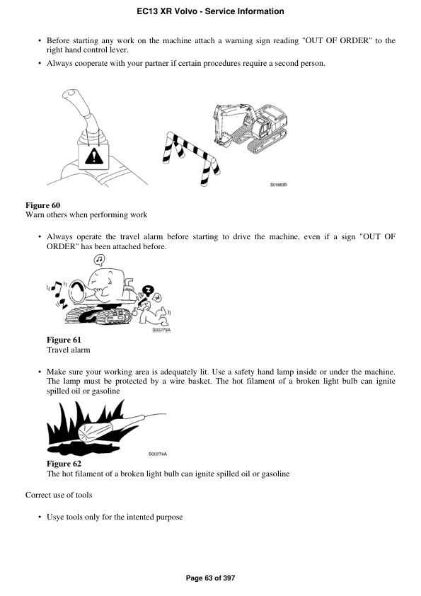
Safety is everybody"s concern!
ENGINE WITH MOUNTING AND EQUIPMENT
General, engine installation and its function
Installing the engine
Removing the engine
ENGINE
General, common info about 211 – 218
Engine performance diagram (measuring values for one hour with fan)
Valve mechanism
Checking the compression pressure
LUBRICATING SYSTEM
General, common info about 221 – 224
FUEL SYSTEM
General (common info about 233 – 238)
Fuel pump; filter; strainer
Bleeding the fuel system
Disassembling the fuel pump
Fuel lines
Assembling the fuel injection line
Disassembling the fuel injection line
Control system; control unit (for ex. injection timming adjuster)
Idle speed, inspection and adjustment
INLET SYSTEM; EXHAUST SYSTEM
Inlet manifold; exhaust manifold
COOLING SYSTEM
Radiator, mounting and connections included
Removing the radiator
Coolant pump; thermostat
Changing the V-belt
Removing the coolant pump
Removing the thermostat housing
Tensioning the V-belt
ELEC. SYSTEM; WARNING SYSTEM; INFORMATION SYSTEM; INSTRUMENTS
Comprehensive info, electrical system
Designations of electrical components
Electric system, trouble shooting
Electrical system, description
Electrical system, technical data
Identification of plug connectors/lines
Line connections in the wiring loom
Marking of plug connectors
Overview digital immobilizer (option)
Precautions when handling plug connectors
Wiring diagram solenoid valve for ariable track (only XTV design)
Wiring diagram travel system solenoid valveł 2 travel speeds
Wiring diagram, slewing/offsetting
Wiring diagrams
BATTERY; ENERGY STORAGE SYSTEM; MOUNTING PARTS
General, common info about 311 – 313
ALTERNATOR; CHARGING; ELECTRIC MOTOR; ELECTRIC DRIVES
General, common info about 321 – 322
Battery, generator, dashboard
Tests before disassembly
Wiring diagram, electric power supply
Alternator inclusive drive
Removing the generator
Charging; converter
Checking the performance characteristics
Checking the voltage regulation
STARTING SYSTEM
General, common info about 331 – 334
Starter, preheating relay, ignition switch
Wiring diagram, starter system
Starter motor inclusive solenoid
Assembling the starter
Dismantling the starter
Installation of the solenoid
Key-operated engine shut down system with EDD-solenoid
Electric air pre-heater, excluding element
Characteristics of the glow plug system
Installing the glow plug
LIGHTING
General, common info about 351 – 356
Boom/roll over protection system
Wiring diagram for lighting
Lighting, extra, including working lighting
Working headlights and main headlights, specification
Working headlights and main headlights, description
OTHER ELECTRICAL EQUIPMENT
General, common info about 361 – 367
Operating/control elements on driverŢ€™s platform
Wiring diagram, socket (12 V)
Audible warning from horn; mounting
Wiring diagram, external warning system
CABLE; FUSE; RELAY
Cable; battery disconnector
Main wiring loom/main plug connector roll over protection structure
Electrical distribution box; fuse box; junction box
Fuses for machine equipment
INSTRUMENT; SENSOR; WARNING AND INFORMATION SYSTEM
General, common info about 383 – 387
Electrical components (hydraulic system side)
Sender, monitoring system
Electrical components (machine side)
Wiring diagram for sensor, control/warning system
Warning/information unit, display unit
Wiring diagram for dashboard
POWER TRANSMISSION
General, common info about 410 – 436
General notes to be observe when working on power transmission assemblies
HYDROSTATIC DRIVE
General, common info about 441 – 443
Technical data
Hydraulic motor incl. operating system.
Travel motor
Disassembling the travel motor
Dismantling the travel gear
Hydraulic motor ހ" slewing of superstructure
Installing the travel motor
Centre passage; lines
BRAKE
TRACK BRAKE
STEERING
Comprehensive info, steering
Steering system, description
FRAME; SPRINGS; DAMPING; AXLE SUSPENSION; WHEEL/TRACK UNIT
FRAME
General, common info about 711 – 718
Frame, technical data
Frame, excavator
Assembling the cylinder for adjustable track width
Assembling the superstructure
Removing the cylinder for adjustable track width
Removing the superstructure
WHEELS; TRACKS; TYRE; HUB; DRUM
General, common info about 771 – 775
Drive gear, tightening torque
Track supporting idler, tightening torque
Crawler unit
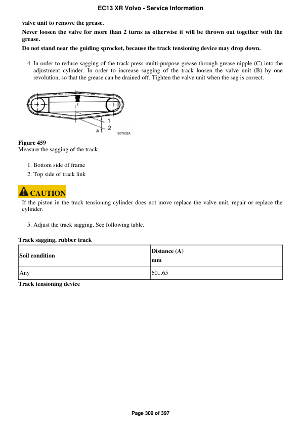
Adjusting the track sagging
Assembling the rubber track
Drive sprocket
Removing the rubber track
Removing the sliding bar
Removing the guide sprocket
MACHINERY HOUSE; CAB; EXTERIOR TRIM PARTS ANYWHERE
Comprehensive info, machinery house and cab
Roll over protection structure
Roll over protection structure, specification
HYDRAULIC SYSTEM; DIGGING/ HANDLING/ GRADING EQUIPM.; MISC. EQUIP.
Hydraulic system, description
WORKING HYDRAULICS; SERVO HYDRAULICS
General, common info about 911 – 917
Adjusting the pressure and checking for leaks
General notes to be observe when working on the hydraulic system
Tank; line; oil cooling; filter; breather; filling pump
Changing the hydraulic oil
Changing the hydraulic oil filter
Checking the hydraulic oil level
Hydraulic oil tank, filling capacity
Removing the oil cooler
Working hydraulics
Adjustment of secondary valves Test and adjustment procedure
Checking and adjusting the breaker (volumetric capacity)
Checking and adjusting the pressure relief valve
Control valve block for slewing gear Test and adjustment
Dismantling the valve block
Hose rupture valve on boom cylinder
Hose rupture valve on boom cylinder Testł andł adjustment procedure
Pressure relief valves
Removing the valve block
Solenoid valve for hydraulic working unit
Test and adjustment values for EC13XR/XTV
Tests and adjustments of the power control
Valve block for slewing gear
Way valve, control valve
Pump, working hydraulics
Removing the hydraulic oil pump
MISCELLANEOUS
General, common info about 992 – 996
Hydraulic circuit for dozer blade and adjustable track width
Return flow, hydraulic circuit for accessories
Share